Pelco Manual C1900M (4/99) 15
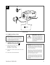
5.0 CAMERA INSTALLATION
ATTENTION
:
Installation should be per-
formed by qualified service personnel only in
accordance with the National Electrical Code
or equivalent/applicable local codes.
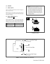
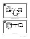
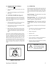
5.1 CONNECTING THE CC3300-2/
CC3300-2X (Illustration F )
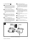
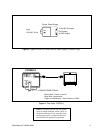
1. Connect the power lines to the camera.
CC3300-2: 24 VAC, 60 Hz
CC3300-2X: 24 VAC, 50 Hz
2. Connect the 75-ohm coaxial cable to the video
monitor.
3. Connect the wall outlet transformer.
CAUTION: CABLE ROUT-
ING. Be sure cable wires are
routed so as to not pinch or rub
when connected to pan/tilt units.
Frayed, pinched or broken wires
can cause fire/shock hazards or
system failure.
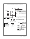
NOTES: When using a transformer without
a ground lead (two-lead type), connect the out-
put of the transformer to the 24 VAC terminals
(1 and 2) of the camera.
When using a transformer with a ground lead
(three-lead type), connect the ground lead to
the GND terminal and the other two leads to
the 24 VAC terminals (1 and 2).
To prevent a short circuit, do not let the ex-
posed transformer leads brush against conduc-
tive material when connecting to the 24 VAC
terminals.
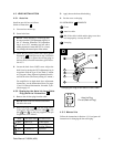
E
1
3
2
4
LOCK
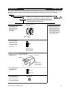
Fitting the Lens


