


C4630M (11/09) 11
Installation
EQUIPMENT PLACEMENT
The DX4104 can be placed on any flat surface (desk or table); the unit is not designed for mounting in an equipment rack.
Position the unit to allow for cable and power cord clearance at the rear of the unit. Be sure that the air flow around the unit is not obstructed.
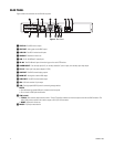
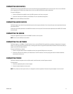
CONNECTIONS OVERVIEW
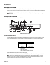
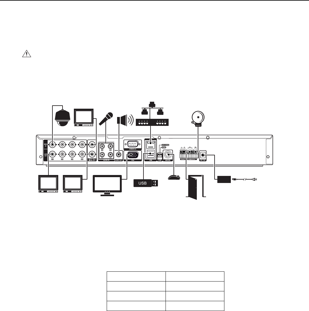
Figure 5 shows the equipment connections for the DX4104.
Figure 5. Connections Overview
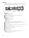
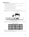
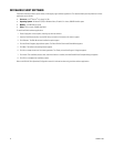
CONNECTING CAMERAS
The DX4104 supports up to four analog cameras. Be sure to disconnect power from each camera before connecting it to the unit. Also, use
75-ohm video coaxial cables with BNC connectors to connect the cameras to the unit. Refer to Table A for coaxial cable requirements.
Connect video cables from up to four cameras to the VIDEO IN connectors.
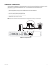
If using the video loop-through option, connect the devices to the VIDEO OUT connectors. Then terminate the video signal at the last device.
NOTE: Operational issues may occur when video devices are not correctly terminated. When connecting camera devices, use a normal
termination of 75 ohms. When using the video loop-through option, make sure the signal is terminated at the last device. For additional
information about terminating a specific device, refer to the device’s installation manual.
WARNING: Do not place the DX4104 on its side. In this position, the unit is likely to fall over and may cause equipment damage or
personal injury.
Table A. Video Coaxial Cable Requirements
Cable Type* Maximum Distance
RG59/U 750 ft (229 m)
RG6/U 1,000 ft (305 m)
RG11/U 1,500 ft (457 m)
*Cable requirements:
75-ohms impedance
All-copper center conductor
All-copper braided shield with 95% braid coverage.