14 PELCO Manual C437M-B (9/95)
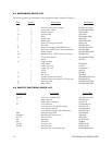
8.0 MECHANICAL PARTS LIST
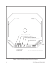
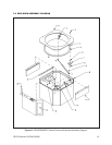
The following parts list corresponds to the exploded assembly diagram in Figure 14.
Item Quantity
Description
Part Number
1 1 Enclosure front plate assembly ED25001003ASSY
2 1 Lower shock mount ED25004005COMP
3 2 Closing fasteners ED2510000
4, 8 8 Nylon washer SB310005
5 1 Dome ED254004COMP
6 4 Roller insert SB310007
7 4 Dome roller SB34020COMP
4 Roller “O” Ring (not shown) ED210100
9 1 Gas shock EH450010020
10 1 Back box assembly (ED25/ED26 only) ED25001000ASSY
1 Back box for ED27 Series only (not shown) ED241000WA
11 2 Heater Bracket ED25004006COMP
11A 4 Heater Blanket, 120/230 VAC (not shown) EHWD10087
12 1 Lower shock bracket ED25004004COMP
2 Spacer SPA8542
13 Light assembly
1 Lamp holder ED210020
1 Lamp, 120 VAC LAP7C7
Lamp, 230 VAC LAP10S6/10
1 Switch SWIV3L
14 1 Blower EH18013
4 Fan spacer SPA8404
15 1 Terminal input circuit board PCB9000255EASSY
1 Terminal input circuit board, 230 VAC only PCB9000255A
16 1 Mounting plate ED25004011COMP
17 1 Hinge spacer ED25004010COMP
9.0 PAN/TILT ELECTRICAL PARTS LIST
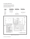
Schematic ID
Description
Part Number
C1–C2 Capacitor, 15 MFD, 100V CAPU0015.0/100N
J1 Input connector CON206044-1
– Mating input connector CONA37S
J2 Lens connector CONMAB6100
Lens connector (SL and PP models) CON206705-1
– Lens mating connector CONMAS6100
Lens mating connector (PP models only) CON206708-1
PCB Interconnecting PCB PCB3000100
Slip Ring Slip Ring (SL models only) 28010000
S1–S4 Limit switches SWI1SM1
M1 Pan motor PT350010010
M2 Tilt motor 2508001
Tilt Pot Preset pot, tilt POTP010.0K
Pan Pot Preset pot, pan POTP010.0K
Preset pot, pan (SL models only) POTDARM010.0K


