TABLE OF CONTENTS
Section Page
1.0 WARNINGS .......................................................................................................................................1
2.0 SCOPE ...............................................................................................................................................2
2.1 DESCRIPTION .........................................................................................................................2
3.0 INSTALLATION ..................................................................................................................................3
3.1 MOUNTING ..............................................................................................................................3
3.2 PAN/TILT INSTALLATION/REMOVAL ....................................................................................4
3.3 ELECTRICAL WIRING ............................................................................................................. 4
4.0 PAN/TILT LIMIT ADJUSTMENTS ...................................................................................................11
5.0 CARE AND MAINTENANCE ...........................................................................................................12
6.0 SERVICE AND REPAIR ..................................................................................................................12
6.1 RECOMMENDED EQUIPMENT AND TOOLS ...................................................................... 12
6.2 SERVICE TIPS .......................................................................................................................12
7.0 EXPLODED ASSEMBLY DIAGRAM ...............................................................................................13
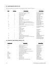
8.0 MECHANICAL PARTS LIST ............................................................................................................14
9.0 PAN/TILT ELECTRICAL PARTS LIST ............................................................................................14
10.0 MODELS ..........................................................................................................................................15
11.0 SPECIFICATIONS ...........................................................................................................................16
11.1 RECOMMENDED MOUNTS/CONTROLS ..............................................................................17
12.0 WARRANTY AND RETURN INFORMATION..................................................................................18
LIST OF ILLUSTRATIONS
Figure Page
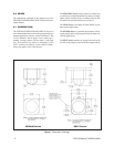
1 Dimension Drawing .........................................................................................................................2
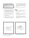
2 FMED25 Installation .......................................................................................................................3
3 PMED25 Installation ....................................................................................................................... 4
4 Power Supply Connection ..............................................................................................................5
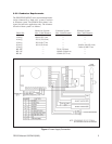
5 ED2520 Series Receiver/Driver Wiring Diagram ............................................................................6
6 ED2620/ED2620-SL Wiring Diagram ............................................................................................. 7
7 ED2520/ED2720 Wiring Diagram ...................................................................................................8
8 ED2520-SL/ED2720-SL Wiring Diagram ........................................................................................8
9 ED2520-PP/ED2720-PP Wiring Diagram ....................................................................................... 9
10 ED2520SL-PP/ED2720SL-PP Wiring Diagram ..............................................................................9
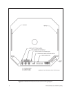
11 Video Synch/Alarm Terminal Diagram .........................................................................................10
12 Tilt Limit Stop Modification ............................................................................................................11
13 Pan Limit Stop Locations ..............................................................................................................11
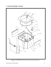
14 ED25/ED26/ED27 Series Enclosure Exploded Assembly Diagram ............................................. 13
REVISION HISTORY
Manual # Date Comments
C437M-A 10/94 Incorporated addendum covering Section 3.3.3, Video Synchronization,
Alarm Terminal Diagram and Figure 11. Incorporated addendum cover-
ing Figure 6, DD2000/DD2000-SL Wiring Diagram.
C437M-B 9/95 Updated Figure 4 and Section 11 to show two (2) 40 Watt heaters per
ECO 95-207. Updated Figure 6 to show correct wiring.
1/96 Figure references in Section 4.0 revised.
ii PELCO Manual C437M-B (9/95)
Pelco, the Pelco Logo, Camclosure, Esprit, Genex, Legacy, and Spectra are registered trademarks of Pelco. © Copyright 1995, Pelco. All rights reserved.
Endura and ExSite are trademarks of Pelco.


