


16 PELCO Manual C460M-E (7/95)
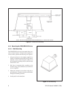
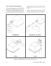
8.0 INSTALLATION
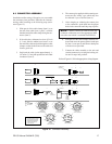
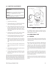
In order to ensure proper wiring and system operation of
all components, it is highly recommended that the pan/
tilt and the associated control equipment be tested in
your facility before field installation is attempted. As-
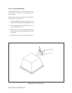
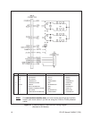
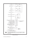
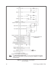
semble the mating connector as outlined in Figure 15
and wire the control cable according to the applicable
diagrams provided in Figures 16 through 17 for all
models except ED28, ED28-1, ED29, ED29-1 and
models with integral receiver (RX or WX). Models with
integral receiver are pre-wired at the factory.
8.1 WIRING
When using a Coaxitron or Wiretron Control System,
consider using the C1906 and C1925 factory assembled
pretested cables which are wired for inverted applica-
tions.
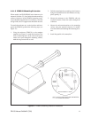
NOTE: If you are not using the C1906 or C1925
pretested cables, you must reverse the left/right and
up/down function pins shown in Figures 16 through
Figure 18.
Cable distances should not exceed the distances speci-
fied in Section 8.2, Conductor/Cable Requirements.
Cable fabrication must be in accordance with Figure 15.
The following are some recommended common instal-
lation practices.
1. Always use jacketed stranded multiconductor in-
terconnecting cable between the control and the
pan/tilt unit, with additional conductors than needed
for future servicing and or additions.
2. Always use color-coded conductors for ease of
wiring and to identify functions at a later date.
3. Keep a wiring diagram with the system for later use
and reference.
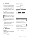
8.2 CONDUCTOR AND
CABLE REQUIREMENTS
Conductors
Conductor requirements are as listed, plus coax cable.
(Standard or SL pan/tilt)
PT2801000ASSY
PT2801001ASSY: Pan/Tilt (5 plus ground)
Lens (4)
Camera AC (2)
(Standard pan/tilt with presets)
PT2801002ASSY: Pan/Tilt (9 plus ground)
Lens (8)
Camera AC (2)
(SL pan/tilt with presets)
PT2801003ASSY: Pan/Tilt (10 plus ground)
Lens (8)
Camera AC (2)
Cable Distances — Hard-Wire Controls
Pan/Tilt Functions
5 Conductors 6 Conductors*
20 Awg 110 feet (33.5 m) 210 feet (64 m)
18 Awg 180 feet (54.8 m) 330 feet (100 m)
16 Awg 290 feet (88.3 m) 530 feet (161 m)
*Using 2 conductor common
Camera Power
Consult the camera manufacturer for transformer power
distances.
NOTE: A relay box (RB24) is available to extend
the operating distance (control to relay box) up to
13,000 feet (3,962 m) utilizing 16 Awg wire.
Cable Distances — Coaxitron
Up to a maximum of 750 feet (228 m) on a single coax
(RG59/U) from the receiver to the transmitter.
NOTE: To extend the distance to 3,000 feet (914m)
on RG59/U coax, use the PELCO EA2000 Half
Duplex Equalizing Amplifier.
Cable Distances — Wiretron
Maximum recommended distances from the receiver to
the transmitter using twisted pair, unshielded cable are
as follows:
22 Awg 5 miles (8 km)
20 Awg 10 miles (16 km)