


PELCO Manual C460M-E (7/95) 21
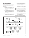
8.4 LIMIT/STOP ADJUSTMENTS
WARNING: Do not operate pan/tilt without limit
stops.
Do not remove or reposition the fixed actuator on
the non-SL. DAMAGE WILL OCCUR.
NOTE: SL models are not equipped with pan limit
stops. (Disregard steps 1-5 below).
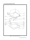
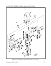
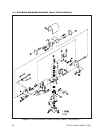
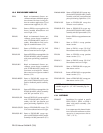
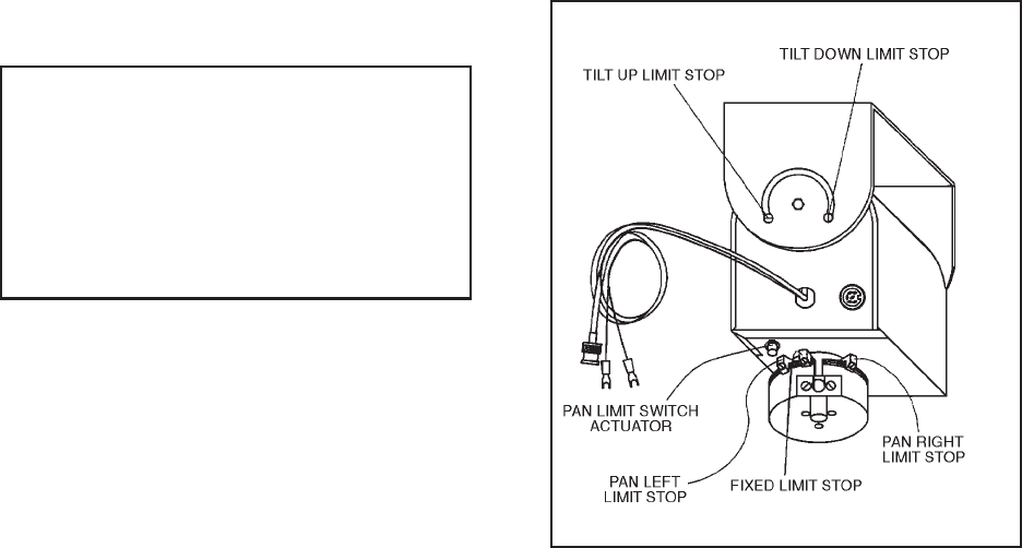
To set limit stops, perform the following steps (refer to
Figure 19).
1. Loosen the pan limit stops.
2. Turn the control unit “on.” Pan the unit to the right
until the desired right pan limit is reached.
3. Move the right pan limit stop until it touches the
pan limit switch actuator. Move the stop a slight
distance further against the actuator until it “clicks”,
indicating opening of the limit switch. Lock the
stop in place.
4. Pan the unit to the desired “left” position. Adjust
the left pan limit stop as described in step 3.
5. Pan left and right to both limit stops and check for
exact positioning. Tighten both stops securely.
6. Remove the end cup from the left side of the tilt
table. Loosen the tilt limit stop screws and tilt the
table, using the joystick, to the desired “up” posi-
tion.
7. Move the “up” limit stop until it touches the tilt
limit switch actuator and “clicks”. Lock the stop in
place.
8. Tilt the table to the desired “down” position and set
the stop in the same manner.
9. Tilt the table up and down and check for exact
positioning. Tighten both stops securely. Replace
the side cover.
After the unit has been tested and stops aligned, turn off
the control and disconnect the AC cord from the outlet.
Remove the multiconductor cable from both the pan/tilt
and control unit. This cable can then be used for instal-
lation by cutting the test cable and splicing the ends onto
the installation cable at the job site. Splice the ends,
color-to-color, onto the cable in the field, using the
terminal blocks at each end.
9.0 OPERATIONAL TEST
9.1 CONTROL
Connect the cable assembly between the pan/tilt and the
control unit. Plug the control unit into the AC outlet and
switch the unit on.
Move the joystick to the UP position. Observing the
“Front” label on the pan/tilt, the front of the tilt table
should move up. Move the joystick to the DOWN
position, and the front of the tilt table should move
down. Releasing the joystick should allow it to return to
center and the tilt table should immediately stop mov-
ing.
Move the joystick to the LEFT position and the com-
plete top assembly should rotate counterclockwise.
With the joystick moved to the RIGHT position, the
unit will rotate clockwise.
Both the pan and tilt motors are protected from me-
chanical over-travel by electrical limits which stop the
motors.
Figure 19. Limit Stops