4 Pelco Manual C478M-L (11/03)
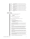
7. Pull the video and power cables through the glands or conduit on the bottom of the en-
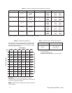
closure. Refer to Tables A and B to determine the size of power wire to use. Refer to
Table C for the type of video coaxial cable to use.
8. Attach the cables to the camera.
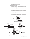
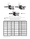
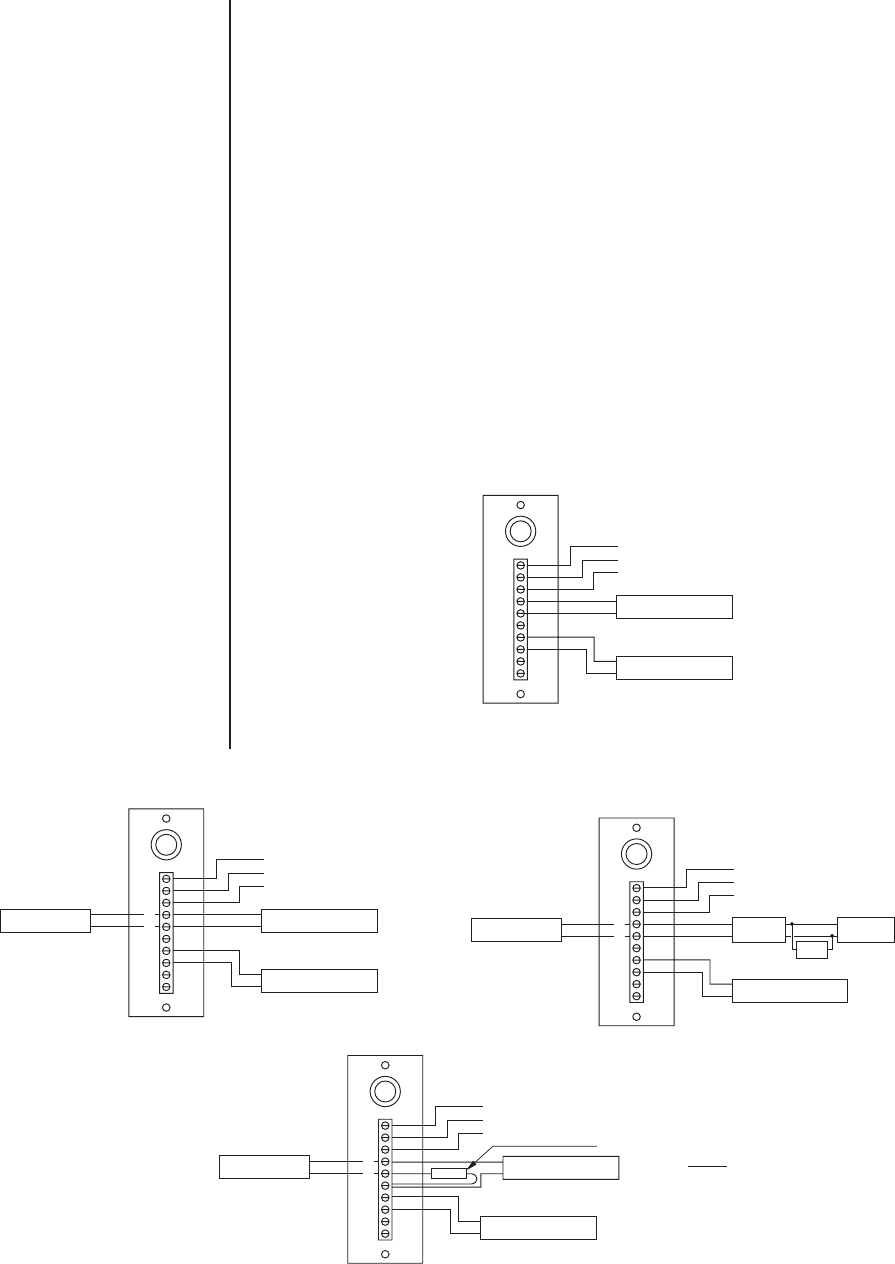
9. If the enclosure has accessories that require power, connect the power to pins 1 and 2
on the PC Board (refer to Figures 1, 2, and 3 for information about accessory wiring).
Connect ground to pin 3 if required.
You can connect the camera power to the PC board if the voltages are the same be-
tween the accessories and camera. If you want to connect the camera power to the PC
board, connect the camera power to pins 1 and 2. Connect ground to pin 3 if required.
10. If the camera lens is adjustable, extend the lens to its maximum length; verify that the
camera is adjusted with the lens a minimum of 1/2 inch from the enclosure window.
11. Tighten the screws that secure the sled to the enclosure.
12. Adjust the glands for a tight fit around the cables.
13. Close the enclosure lid, and latch.
14. Adjust the camera focus and iris if necessary. If you need to adjust the focus and iris
manually, open the enclosure lid, adjust the focus and iris, and close the enclosure lid.
1
2
3
4
5
6
7
8
9
10
HEATER
DEFROSTER
INPUT, AC HIGH
INPUT, AC LOW (NEUTRAL)
GROUND
Figure 1. EH3508-1/-2/-3 Wiring Diagram
1
2
3
4
5
6
7
8
9
10
INPUT, AC HIGH
INPUT, AC LOW (NEUTRAL)
GROUND
120 VAC MODELS
DEFROSTER
BLOWER
HEATER
1
2
3
4
5
6
7
8
9
10
HEATER
DIODE
BRIDGE
INPUT, AC HIGH
INPUT, AC LOW (NEUTRAL)
GROUND
24 VAC MODEL
DEFROSTER BLOWER
RED
BLK
RED
BLK
CAP
Figure 2. EH3512-1/-1HD/-2/-2HD/-3/-3HD Wiring Diagram
1
2
3
4
5
6
7
8
9
10
INPUT, AC HIGH
INPUT, AC LOW (NEUTRAL)
GROUND
230 VAC MODEL
DEFROSTER
HEATER
120 VAC BLOWER
RESISTOR
24/120/230 VAC
MODELS
NOTE: BLOWER APPLIES
TO -1/-2/-3 MODELS ONLY.


