4 Pelco Manual C483M-E (9/97)
3.0 INSTALLATION
Before installing the HS3000/HS3020 to a wall or ceiling, make certain that the
mounting surface is able to support four times the full load of the enclosure plus all
other equipment such as camera, lens, etc.
To mount the enclosure to a wall or ceiling, follow the steps outlined below.
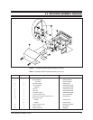
1. Unscrew the screws and remove the cover using the special socket (fits 1/4"
drive) and Allen wrench that are provided.
2. Knock out any of the three (3) cable entry holes desired on the enclosure
body.
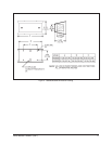
3. Mark and drill four (4) holes in the wall or ceiling for mounting the enclosure
and, as required, holes for cabling (see Figure 2 dimension drawing).
4. Attach the enclosure with the required fasteners.
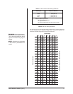
5. Route all cables through the appropriate knockouts. Refer to Table A for the
type of video coaxial cable to use. If your camera will use 24 VAC power, refer
to Table B to determine the size of wire to use. If you are using conduit, attach
it to the enclosure.
6. The tilt table consists of two (2) L-brackets. If the enclosure is mounted to a
wall, remove the outer L-bracket.
7. Loosen the tilt table mounting bolt.
8. Securely attach the camera/lens to the desired location on the tilt table using
the bolts, flat washers and split lock washers that are provided.
9. Make all necessary electrical connections (video, camera power, etc.).
10. Wire the tamper switch. For a “Normally Open” circuit, use the “NO” and “com-
mon” terminals; for a “Normally Closed” circuit, use the “NC” and “common”
terminals. Remember that the switch will be pushed down when you replace
the cover.
11. Position the tilt table at the desired location and angle, and tighten the hard-
ware.
12. Replace the cover.
13. Provide power to the camera and check for adequate video image.
NOTE:
The four (4) fasteners re-
quired to secure the enclosure to
a wall mounting surface (minimum
3/8" [.952 cm] diameter recom-
mended) are not supplied.


