


C3418M-B (11/06) 3
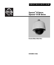
1. Install the mount for the pendant dome. Refer to the instructions supplied with the mount.
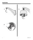
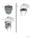
2. Open the hinged door to the back box. Push the tab lock towards the wall of the unit and lift the door open. Pull
wiring into the back box. Refer to Table A, Table B, and Table C for wiring distances.
3. Screw the back box onto the mount. If outdoors, apply thread compound (provided) to the threads on the back box.
NOTE: Thread compound must be applied. Not doing so may prevent the units from being separated in the future.
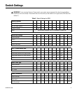
..
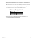
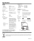
Note: Input power for the dome is 24 VAC or 24 VDC. Using 24 VAC input power, power consumption is 23 VA per dome
for indoors models and 73 VA for out models. Using 24 VDC input power, power consumption is 0.7 A (15 watts) for indoor
models and 3 A (65 watts) for outdoor models.
Use a 24 VAC transformer with the following minimum VA:
40 VA per dome For indoor models (without heater)
100 VA per dome For outdoor models (with heater)
NOTE: As a minimum, UTP requires Cat5, 100-ohm twisted pair cable
Table C. UTP Wiring Distances
Receiver Maximum Distance
Active
(Video Only)
0-3,000 ft
(0-914.4 m)
Passive
(Video, Coaxitron, Pelco V-Sync)
0-750 ft
(0-228.6 m)
*Cable requirements:
75 ohms impedance
All-copper center conductor
All-copper braided shield with 95% braid
coverage
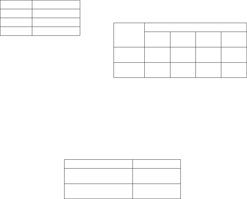
Table A. Video Coaxial Cable
Requirements
Cable Type* Maximum Distance
RG59/U 750 ft (229 m)
RG6/U 1,000 ft (305 m)
RG11/U 1,500 ft (457 m)
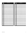
Table B. 24 VAC/24VDC Wiring Distances
The following are the recommended maximum distances for 24 VAC
and 24 VDC applications and are calculated with a 10 percent voltage
drop. (Ten percent is generally the maximum allowable voltage drop
for AC- or DC-powered devices.)
AC/DC
Total VA/
Total Watts
Wire Gauge
20 AWG
(0.5 mm
2
)
18 AWG
(1.0 mm
2
)
16 AWG
(1.5 mm
2
)
14 AWG
(2.5 mm
2
)
23 VA/
15 watts
123 ft
(38 m)
196 ft
(60 m)
311 ft
(95 m)
495 ft
(151 m)
73 VA/
65 watts
39 ft
(12 m)
62 ft
(19 m)
98 ft
(30 m)
156 ft
(48 m)