Pelco Manual C1905M (10/99) 5
INSTALLATION
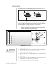
The lens must be either a C- or CS-mount type of less than 2.2 pounds (1 kg). The protru-
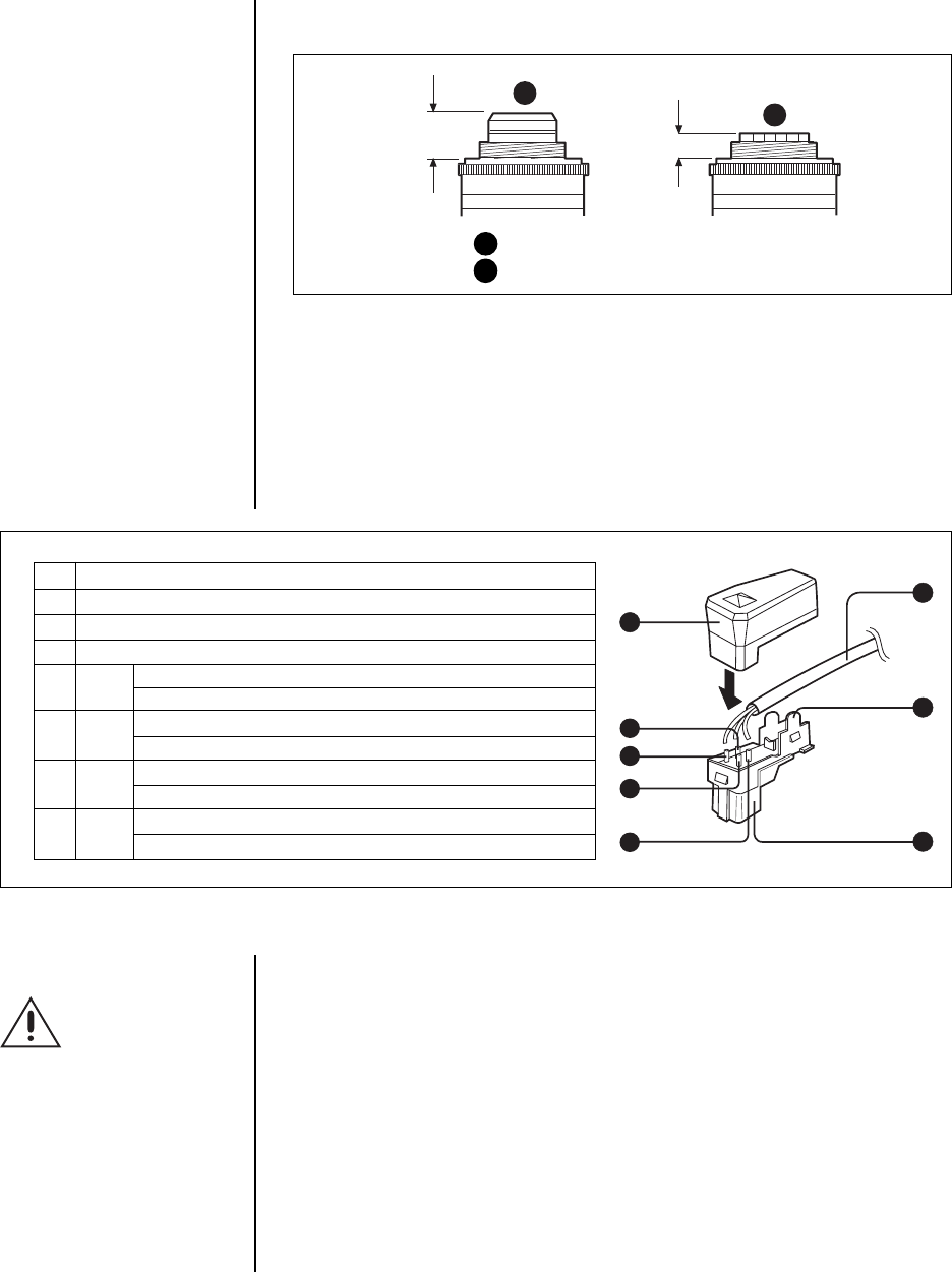
sion behind the mounting surface must be within the limits as shown in Figure 3.
The camera is supplied with a lens connector for inserting the power and control cable of
an auto iris lens. Before connecting an auto iris lens, however, you first have to replace the
lens cable plug with the one supplied with this camera. To replace the plug:
a. Detach the old plug from the lens cable.
b. Solder the wires to the pins of the new plug (refer to Figure 4). For cable pin as-
signments, refer to the instruction manual for the lens.
Figure 4. Replacing Lens Plug
1Cover
2 Lens cable (not supplied)
3 Rib (If the cable is thick, cut this off.)
4 Plug (supplied)
5 Pin 4 Video signal control: Ground
DC control: DRV-
6 Pin 2 Video signal control: Not used
DC control: CONT+
7 Pin 1 Video signal control: Power supply (9 VDC, 50 mA maximum)
DC control: CONT-
8 Pin 3 Video signal control: Video signal (0.7 Vp-p)
DC control: DRV+
2
3
4
1
8
7
6
5
1. Unscrew the lens mount cap.
2. Loosen the locking screw. According to the type of lens, adjust the focal length by turn-
ing the focal length adjustment ring. Re-tighten the locking screw.
3. Screw in the lens, and turn it until it is secure.
4. Insert the lens plug in the LENS connector. Skip this step if you are installing a manual
iris lens.
5. Mount the camera.
6. Connect a 75-ohm coaxial cable from the VIDEO OUT connector on the camera to the
VIDEO IN connector on a video monitor or other video input.
7. Connect the camera to a 24 VAC, 60 Hz, Class 2 power supply.
CAUTION:
Keep
the lens mount cap
on the camera
when a lens is not attached.
Figure 3. Lens Mounting Dimensions
1
1)
2)
2
1 C-mount lens 0.35-inch (9 mm) or less
2 CS-mount lens 0.16-inch (4 mm) or less


