


6 C1963M (8/04)
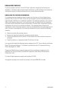
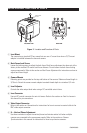
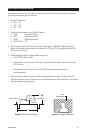
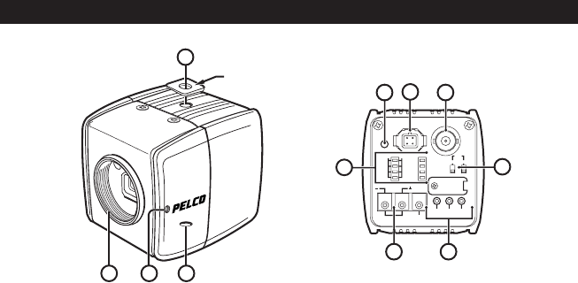
LOCATION AND FUNCTION OF PARTS
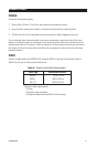
ᕃ Lens Mount
The camera has a standard CS lens mount but can use a C-mount lens when a C/CS-mount
adapter is installed between the lens and camera.
ᕄ Back Focus Lock Screw
Loosen the locking screw to adjust the back focus. Back focus adjustment has been set at the
factory to the standard CS-mount back focus distance. Do not loosen the back focus locking
screw unnecessarily. Refer to the section on
Back Focus Adjustment
for instructions on how to
adjust back focus length.
ᕅ Camera Mounts
Mounting points are provided on the top and bottom of the camera. Maximum thread length is
3/16-inch. Attach the camera mount adapter to extend thread depth to a standard 1/4-inch.
ᕆ Level Adjuster
Controls the video output level when using a DC-controlled auto iris lens.
ᕇ Lens Connector
Four-pin DC-control connector for auto iris lenses. Refer to the section on
Auto Iris Lenses
in
this manual for pin connections.
ᕈ Video Output Connector
Refer to the section on
Connections
for instructions for how to connect a coaxial cable to the
BNC video output connector.
ᕉ LL – Vertical Phase Adjustment
Use these switches to adjust the vertical phase to eliminate vertical roll when multiple
cameras are connected to the same power supply. Refer to the section on
Camera
Synchronization
in this manual for instructions on how to synchronize cameras.
Figure 1. Location and Function of Parts
TOP/FRONT VIEW BACK VIEW
3
321
CAMERA MOUNT
ADAPTER
7
10
LL
THRE ECLP GRAY
VIDEOLENS
LEVEL
OFF ON
UP DOWN
AWB
SYNC
GAM
FL
AGC
ESC
BLC
ECLP
DC12V
24VAC GND
5
6
4
89