Pelco Manual C233M-G (8/95) 5
NOTE:
When determining the
mounting location, consideration
must be given to the total weight of
the monitor and the mount. The
mounting surface must be adequate
to support this weight.
3.2 MRU ASSEMBLY INSTRUCTIONS
3.2.1 Hanger Assembly
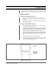
1. Fit together the top bracket and the two side arms and place over the monitor/
receiver. Adjust each side arm equally outward to align the fastener holes.
Using the four (4) 1/4-20 x 5/8 hex bolts, flat washers, lock washers and hex
nuts supplied, fasten the arms to the top bracket.
2. Remove the monitor from the hanger assembly.
3. Thread the mounting pipe with the long-threaded section of pipe with hole for
cotter pin into the top bracket, insert cotter pin, and tighten the 8-32 screw in
the pipe nut to lock the pipe threads.
3.2.2 Mounting the Hanger Assembly
1. Determine the location for, and the type of mount to be used. Remember to
allow for adequate clearance on all sides of the monitor.
2. Use the adapter mount as a template to mark the required mounting holes.
3. Using the necessary fasteners, attach the adapter mount to the chosen sur-
face.
4. Thread the mounting pipe into the mount, stopping at the desired position,
after the threads have become tight, approximately 30 ft lb. (If the MRCA or
MRWA is being used, tighten the 8-32 screw in the pipe nut to lock the pipe
threads.)
3.2.3 Monitor Mounting
1. Align the holes in the side arms of the monitor bracket with the threaded holes
in the side of the monitor/receiver.
2. Attached the monitor/receiver to the mount with the supplied fasteners
3. Tilt the monitor to the desired angle and tighten the fasteners.
4. Make all necessary electrical connections.


