


2 Pelco Manual C325SM (3/99)
REVISION HISTORY
Manual # Date Comments
C323SM 10/98 Original version.
3/99 Revised Figure 3 preset pinouts, pins 2 and 9, for up/
down and right/left functions.
LIST OF TABLES
Figure Page
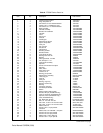
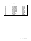
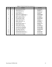
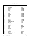
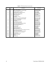
A PT550P Series Parts List...................................................................9
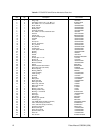
B PT570P/PT570-24P Series Mechanical Parts List ...........................12
C PT570P/PT570-24P Series Hardware List .......................................13
D PT573 Series Parts List....................................................................15
E PT680-24P and PT680-24P/PP MechanicalParts List .....................19
F PT680-24SL and PT680-24SL/PP Mechanical Parts List ................20
G PT680-24 Series Hardware List........................................................21
H PT550P Electrical Parts List .............................................................22
I PT550P/PP Electrical Parts List .......................................................23
J PT570P Series Electrical Parts List ..................................................24
K PT570-24P Series Electrical Parts List.............................................24
L PT573 Series Electrical Parts List ....................................................25
LIST OF ILLUSTRATIONS
Figure Page
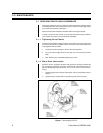
1 Servicing the Pan/Tilt .........................................................................6
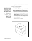
2 Sealant Locations ..............................................................................7
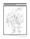
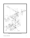
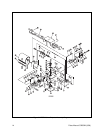
3 PT550P Series Exploded Assembly Diagram....................................8
5 PT573 Series Exploded Assembly Diagram .....................................14
6 PT680-24P and PT680-24P/PP Exploded Assembly Diagram.........17
7 PT680-24SL and PT680-24SL/PP Exploded Assembly Diagram .....18
8 PT550P Wiring Diagram ...................................................................22
9 PT550P/PP Wiring Diagram .............................................................23
10 PT570P/PT570-24P Series Wiring Diagram .....................................24
11 PT573 Series Wiring Schematic .......................................................25
12 PT680-24P Wiring Schematic...........................................................26
13 PT680-24SL Wiring Schematic .........................................................27
14 PT680-24P/PP Wiring Schematic .....................................................28
15 PT680-24SL/PP Wiring Schematic ...................................................29
16 PT680-24P/HB Wiring Schematic.....................................................30
17 PT680-24SL/HB Wiring Schematic ...................................................31
CONTENTS
Section Page
1.0 GENERAL ..................................................................................................3
1.1 IMPORTANT SAFEGUARDS AND WARNINGS ...............................3
2.0 DESCRIPTION ..........................................................................................4
2.1 MODELS ............................................................................................4
2.2 OPTIONS...........................................................................................5
3.0 MAINTENANCE .........................................................................................6
3.1 SERVICING DRIVE CHAIN ASSEMBLIES .......................................6
3.1.1 Tightening Drive Chains ..........................................................6
3.1.2 Chain Drive Lubrication ...........................................................6
3.2 RESETTING POTENTIOMETERS ....................................................7
4.0 EXPLODED ASSEMBLY DIAGRAMS .......................................................8
5.0 WIRING DIAGRAMS ................................................................................22
6.0 WARRANTY AND RETURN INFORMATION ...........................................32