


Pelco Manual C325SM (3/99) 7
3. Apply additional grease if necessary.
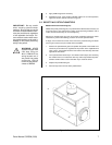
4. Reinstall the cover. If the pan/tilt is installed outdoors in an inverted position,
apply RTV silicone sealant as shown in Figure 2.
3.2 RESETTING POTENTIOMETERS
Models with Preset Positioning (PP)
Models with preset positioning (PP) use potentiometer switches that are factory set
to the full range of pan and tilt travel. Under normal operating conditions and at
routine service intervals they do not need adjusting.
Should your pan/tilt require any work on the drive mechanism other than routine
maintenance, perform the following procedure to reset the potentiometers.
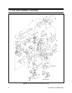
To begin, remove the three screws on the front of the pan/tilt housing and lift the
cover to gain access to the pan and tilt motor assemblies.
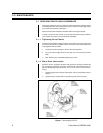
1. Remove the potentiometer gears and position the pan/tilt to the middle of its
maximum pan and tilt travel, regardless of the position of the adjustable limit
stops. That is, the tilt table should be level and the fixed limit stop should be
opposite the limit switch.
2. Turn a potentiometer all the way in one direction until it stops, then observing
the number of turns, turn it back the other way until it stops. Rotate the poten-
tiometer half the number of turns the other way to reach the center.
3. Replace the potentiometer gear.
4. Perform steps 2 and 3 for the other potentiometer.
Figure 2. Sealant Locations
➛
➛
➛
IMPORTANT:
Be very careful
when resetting potentiometer
switches. Be sure that the pan/tilt
has been centered between maxi-
mum pan and tilt travel, regardless
of the adjustable limit stops. Fail-
ure to observe caution when reset-
ting potentiometers could result in
damage to the preset positioning
ability of the pan/tilt.
WARNING:
NEVER
reposition the pan fixed
limit stop. Doing so
WILL DAMAGE the
wiring harness and, if
the pan/tilt has preset
positioning, COULD
cause the pan potenti-
ometer to BREAK.