


10 Pelco Manual C342M-D (8/05)
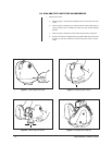
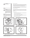
3.3 ENCLOSURE INSTALLATION
Attach the camera enclosure to the pan/tilt unit. Follow the instructions that are
provided with the enclosure.
3.4 ELECTRICAL INSTALLATION
3.4.1 LRD41 Series Legacy
®
Receiver/Drivers
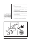
Connect the 37-pin round connector from the pan/tilt unit to the mating connector
on the receiver/driver.
3.4.2 All Control Equipment Except LRD41 Series Legacy
®
Receiver/Drivers
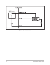
Make the interconnecting cable to link the 37-pin round connector from the pan/tilt
unit to the control equipment.
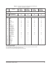
For cable requirements, refer to the following tables and chart:
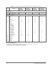
Table A-1: Connector Pin Designations for Pan/Tilts with EH4700L
and EH5700L Enclosures
Table A-2: Connector Pin Designations for Pan/Tilts with EH8106L
Enclosures
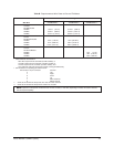
Tables Band C: Requirements to Wire Power to Pan and Tilt Motors
Table D: Requirements to Wire Power to Camera Enclosure
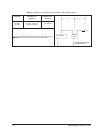
Table E: Requirements to Wire Power to Optional Heater Blanket
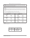
Table F: 24 VAC Wiring Distances Chart
The following are some recommended common installation practices:
• For unshielded conductors, use jacketed, stranded, multiconductor cable, with
additional conductors than needed for future servicing and/or additions. Use
color-coded conductors for ease of wiring and to identify functions at a later
date.
• Keep a wiring diagram with the system for later reference.