


14 C3446M (7/08)
RECESSED INSTALLATION
SUSPENDED CEILING
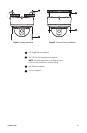
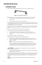
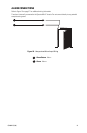
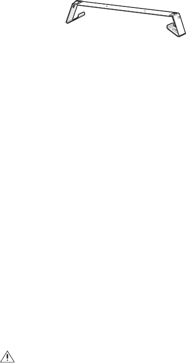
1. Remove the spring paddle flex assembly from the surface mount ring (refer to Figure 7).
Figure 7. Spring Paddle Flex Assembly
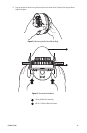
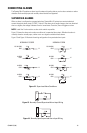
2. Remove the surface mount ring from the dome drive as follows (refer to Figure 8 on page 15):
a. Place fingers on the circular marks located on the sides of the surface mount ring.
b. Pinch the sides.
c. Lift and remove the surface mount ring from the dome drive.
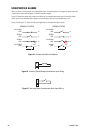
3. Attach the spring paddle flex assembly to the dome drive using the two #8-32 x 3.50-inch machine
screws (supplied). Thread the screws into the ends of the spring paddle flex assembly flex assembly
so the paddles remain at the end of the screws.
4. Cut a 5-inch diameter hole in the ceiling tile. You can either use the two holes in the spring paddle
flex assembly as a compass tool to mark the 5-inch diameter hole to be cut, or use a 5-inch hole
saw.
5. Pull all wiring through the hole in the ceiling tile and terminate all wires.
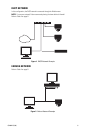
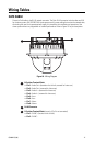
6. Connect your wiring to the dome drive using one of the following options:
• Plug the network cable into the RJ-45 connector on the side of the dome drive.
• If the network has no PoE, connect a 24 VAC Class 2 power supply to the 24 VAC power
connector.
Refer to Figure 10 on page 17 for wiring connections.
7. Attach the dome drive to the ceiling tile, (refer to Figure 9 on page 15).
a. Stabilize the spring paddle flex assembly by applying pressure to the machine screws.
b. With the screws stabilized, insert the spring paddle flex assembly and dome drive into the
hole in the ceiling tile.
NOTE: Be sure to route all wiring away from the spring paddle flex assembly.
c. Once the spring paddle flex assembly has cleared the hole in the ceiling tile, release the
machine screws and allow the spring paddle flex assembly to expand. You do not need to
support the dome drive as the ends of the paddle will hold the dome drive in place.
d. Tighten the machine screws completely to secure the ceiling tile between the spring paddle
flex assembly and the dome drive.
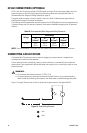
8. If you are operating the dome system using 24 VAC and you are wiring more than one dome drive to
the same transformer, connect one side of the transformer to pin 1 of the 2-position terminal block
on all modules. Connect the other side of the transformer to pin 2 of the terminal block on all
modules.
NOTE: Failure to connect all modules identically may introduce noise in the video for some
installations.
WARNING: Do not overtighten the mounting hardware; doing so can impede the pan
movement of the dome drive.