


18 C3446M (7/08)
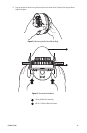
24 VAC CONNECTIONS (OPTIONAL)
If PoE is not used, the camera includes a 24 VAC power connector. Connect the power cable to the 2-pin
power connector on the back of the camera using the terminal block connector (provided). Refer to
Recommended Wire Gauge and Wiring Distances on page 18.
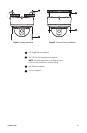
The power supply connector is shown in Figure 6. Use only a Class 2 isolated power supply. Refer to
Specifications on page 25 for power consumption.
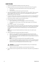
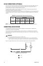
The following are the recommended maximum distances for 24 VAC applications and are calculated with a
10 percent voltage drop. (Ten percent is generally the maximum allowable voltage drop for AC-powered
devices.)
NOTE: Power consumption is 18 VA per unit. Use a power source with a minimum of 18 VA per unit.
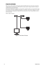
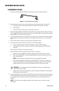
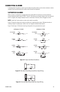
CONNECTING A RELAY DEVICE
The Spectra Mini IP dome system has an output for triggering an external device. It supports both
momentary and continuous relay operation.
You can operate the relay interactively, during an active connection, or automatically to coincide with
certain events. Typical applications include activating a door, gate or lock, or switching on lights or other
electrical devices.
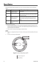
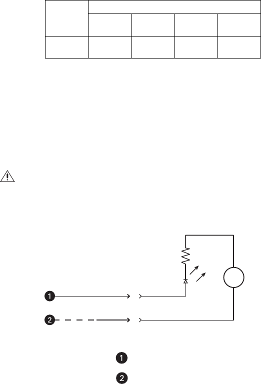
Figure 11 on page 18 shows how to wire the relay with its power source to the Spectra Mini IP.
Figure 11. Relay Wiring Example
Table B. Recommended Wire Gauge and Wiring Distances
Voltage
Wire Gauge
18
(1.0 mm
2
)
16
(1.5 mm
2
)
14
(2.5 mm
2
)
12
(3.5 mm
2
)
24 VAC 215 ft
(97 m)
341 ft
(154 m)
542 ft
(245 m)
863 ft
(391 m)
WARNINGS:
• Do not exceed the maximum rating of 12 VDC, 0.15 A.
• The green/white wire is internally connected to the dome chassis. Any connected signaling
device should be left floating with respect to the dome chassis, otherwise damage may result.
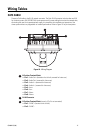
Aux -
Aux +
+
_
DC