


OPERATIONS
16
CARETAKER PLUS INSTALLATION AND OPERATIONS MANUAL
Initial State
Following the successful completion of the power up tests, the Caretaker Plus turns all
the port LEDs off. The BUSY LED may be lit if the shared device is busy.
Normal Operation
Input devices, usually computers, initiate requests to connect to the shared device by
sending data to the Caretaker Plus. If no other ports are currently connected, connection
with the shared device is made immediately. If other ports are currently connected, the
requesting port must wait for all other ports ahead of it to use the shared device before it
will be connected. An input device may send data to the unit's buffer while it is waiting to
be connected.
When data is received from the currently connected port, it is sent to the shared device if
it is not busy; otherwise, the data is stored in the buffer until the shared device becomes
ready. Data from a queued port is stored in the port's buffer until the port becomes
active; at that time, the data is sent to the shared device whenever it is not busy. For
serial models only, data that is received from the shared device is sent to the currently
connected port if it is not busy; otherwise, the data is stored in the buffer until the port
becomes ready.
For serial models, when a port is connected to the shared device, full duplex
communication is in effect; data can flow in either direction between the connected port
and the shared device. For parallel models, data can flow only in one direction, from the
connected port to the shared device.
The LED corresponding to the port currently connected to the shared device will flash
and LEDs corresponding to ports waiting for use of the shared device will be lit steadily.
If no data is sent to or from the currently connected port for the duration of the timeout
setting and the shared device and the connected input device are not busy, the current
port will be disconnected and its LED will go from the flashing state to the unlit state. The
next port in the queue will become connected and its LED will go from the steadily lit
state to the flashing state. Any data sent to the buffer while waiting will now be sent to
the shared device.
The timeout is reset by four possible conditions:
1. Data is transmitted by the connected input device
2. Data is transmitted by the shared device (if REVERSE CHANNEL DATA TIMEOUT is
enabled)
3. The shared device is busy
4. The connected input device is busy (if TIMEOUT ON BUSY is disabled). The timeout
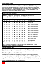
period begins only when none of these conditions exist. To determine the state of the
unit by its LEDs see TABLE 5.