


CARETAKER PLUS INSTALLATION AND OPERATIONS MANUAL
17
Buffer Characteristics
The switch may have a buffer memory of 16K, 256K, 512K, 1 megabyte,
or 2 megabytes. The Caretaker Plus uses an intelligent algorithm to allocate memory.
The buffer is dynamically allocated which means that any port can utilize as much buffer
as required. The buffer is reclaimed to be used again as the data in the buffer is sent to
its destination. As the memory becomes full, the reclaimed memory is first distributed to
a currently active port, then to the queued ports as needed. However, the currently
active port always has priority over the queued ports for memory. If the memory used for
the queued ports becomes full, the queued ports are flow controlled off until the
memory available for the queued ports becomes available. If all the memory available
becomes full, the active port is flow controlled off until some memory becomes available.
The buffer is divided in 32 memory allocation units. Each input port will always have one
memory unit allocated to it.
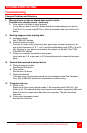
Unit Software Reset Function
By entering and then immediately leaving configuration mode, (pressing both switches
and releasing them to illuminate the MODE and BUSY LEDs, then pressing them again),
a software reset is performed. All buffers are flushed; flow control flags are reset, and
the unit restarts normal operation.
Printer Initialization Signal (Parallel Models Only)
At the completion of the power up test on parallel models, the INIT signal on the parallel
interface is pulsed. This resets most printers.
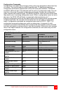
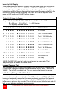
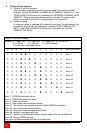
Table 5. LED operation Display
Legend: M = Mode LED D = Data LED B = Busy LED E = Error LED
● = LED on O = LED off ☼ = LED flashing
X = may vary, described below
M D B E 1 2 3 4 5 6 7 8 EXPLANATION
O O O O O O O O O O O O Note 1
O X X X X X X X X X X X Note 2
● X X O X X X X X X X X Note 3
● X ● O O O O O O O O O Note 4
● ● ● O O O O O O O O O Note 5
O O X ☼ X X X X X X X X Note 6
Note 1: Normal operation - unit is idle. All LEDs off.
Note 2: Normal operation - unit handling data. Data LED is on when data being transmitted or received
on the shared device. Busy LED is on when the shared device is busy. Error LED is on when a parallel
unit has an Interface error. Port LEDs fash when connected to shared device; glow steadily when
waiting for connection.
Note 3: Normal operation - unit in Row control display mode. Data LED operates as above. Busy LED
lights when the shared device input buffer is full. Port LEDs light when the corresponding buffer is full.
Note 4: Unit in configuration mode. Data LED lights in response to data input on Port 1.
Note 5: Unit is in configuration mode and the menu is in use.
Note 6: Buffer overflow has occurred. Port LEDs corresponding to overflowed ports will Rash rapidly in
unison with the Error LED. Busy LED flashes in unison with the Error LED to indicate an overflow on the
shared device's input buffer.