12 – DIGITAL COLOR CAMERA
Installation
CONNECTING CABLES AND
CHECKING OPERATION
①
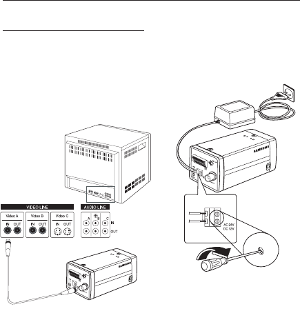
Connect one end of the BNC cable to the
VIDEO OUT Port on the rear of the camera.
② Connect another end of the BNC cable to the
VIDEO IN Port on the monitor.
③
Finally connect the power adapter to the
camera. You can connect 2 lines of the power
adapter to the camera using the Slot Head
screwdriver as shown in the picture.
(GND: cable with the white stripe line)
1 2
3 4
5 6
7
8
1
.
A
L
A
R
A
M
O
U
T
2
.
G
N
D
3
.
G
N
D
4
.
S
H
U
T
T
E
R
(
S
O
)
5
.
S
H
U
T
T
E
R
(S
1
)
6
.
S
H
U
T
T
E
R
(S
2
)
7
.
5
V
O
U
T
8
.
D
A
Y
/
N
I
G
H
T
I
N
Note :
Connect any power source of AC 24V and DC 12V
irrespective of polarity.
–
1
2
3
4
5
6
7
8
1
.
A
L
A
R
A
M
O
U
T
2
.
G
N
D
3
.
G
N
D
4
.
S
H
U
T
T
E
R
(
S
O
)
5
.
S
H
U
T
T
E
R
(
S
1
)
6
.
S
H
U
T
T
E
R
(
S
2
)
7
.
5
V
O
U
T
8
.
D
A
Y
/
N
I
G
H
T
I
N
Video In Terminal of Monitor Rear
Surface
BNC cable
Video Out Terminal
USI
E
B
sa
R
R
U
P
O
e
U
P
O
re
•
•
•
•
•


