


10 – DIGITAL COLOR CAMERA
Introduction
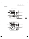
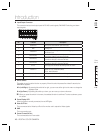
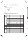
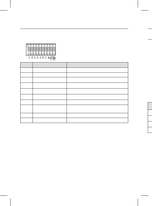
n Input/Output Connector
This connector has input and output ports for RS-485 control signals, DAY/NIGHT switching, and alarm
output signals.
No. Function Description
1 ALARM OUT
Alarm out port for motion detection. (Open collector type)
2 GND Grounding Port.
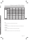
3 TRIGGER IN
Displays the current still image when it receives the Trigger signal.
(Normal Open Type)
4 SHUTTER (S0)
This is a port for selecting an external high speed shutter mode.
If connected in LOW (0V), it will become ON inside.
5 SHUTTER (S1)
This is a port for selecting an external high speed shutter mode.
If connected in LOW (0V), it will become ON inside.
6 SHUTTER (S2)
This is a port for selecting an external high speed shutter mode.
If connected in LOW (0V), it will become ON inside.
7 5V OUT
Power supply port for RS-485 JIG. Use within typical DC +5V 100mA
8
DAY/NIGHT IN
This is a port for DAY&NIGHT conversion.
High(DC +3V~+5V) : DAY(COLOR) Mode,
Low(0V) : NIGHT(BW) Mode
9 RS-485 DATA-
This is a port for connection to RS-485 DATA- signal line.
10 RS-485 DATA+
This is a port for connection to RS-485 DATA+ signal line.
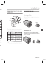
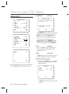
o SETUP Switch
This switch is used to set the function or property. When this switch is pressed for at least 2 seconds, the
MAIN MENU appears.
ef
(Left/Right)
: By pressing this switch left or right, you can move left or right on the menu or change the
displayed value.
cd
(Up/Down) :
By pressing this switch up or down, you can move up or down on the menu.
: When you press this switch in the menu, the selected function is confi rmed. To enter a submenu, press
this button.
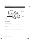
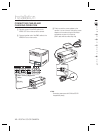
p Power Display LED
When the power is normally connected, the red LED lights.
q Video OUT Port
This is connected to the Video Input Port of the monitor and it outputs the Video signals.
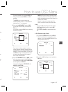
r GND
This is a grounding port.
s Power Connection Port
This is connected to the Power cable.
CO
CO
Conn
the A
P
N
1
2
3
4
No
–