6
Mount the unit in a suspended ceiling grid using the existing
ceiling tile as follows:
1. Remove tile at desired location.
2.
Cut a 172 mm (6.75-inch) diameter hole in the center of
the tile
. Use two pencils (or a pencil and a nail) with the
template tool provided to draw the circle.
3. Connecting Low Voltage Power & Video:
NOTE: Power and video can be connected before or after
unit is mounted into the ceiling.
a. Prepare the low voltage wires by stripping 9-11 mm
(0.39-inch) from each wire.The push-wire connector is
designed to accommodate AWG 20-16 wire.
b. Connect the line and neutral wires.
c. Route and connect video cable to BNC connector.
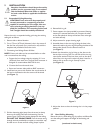
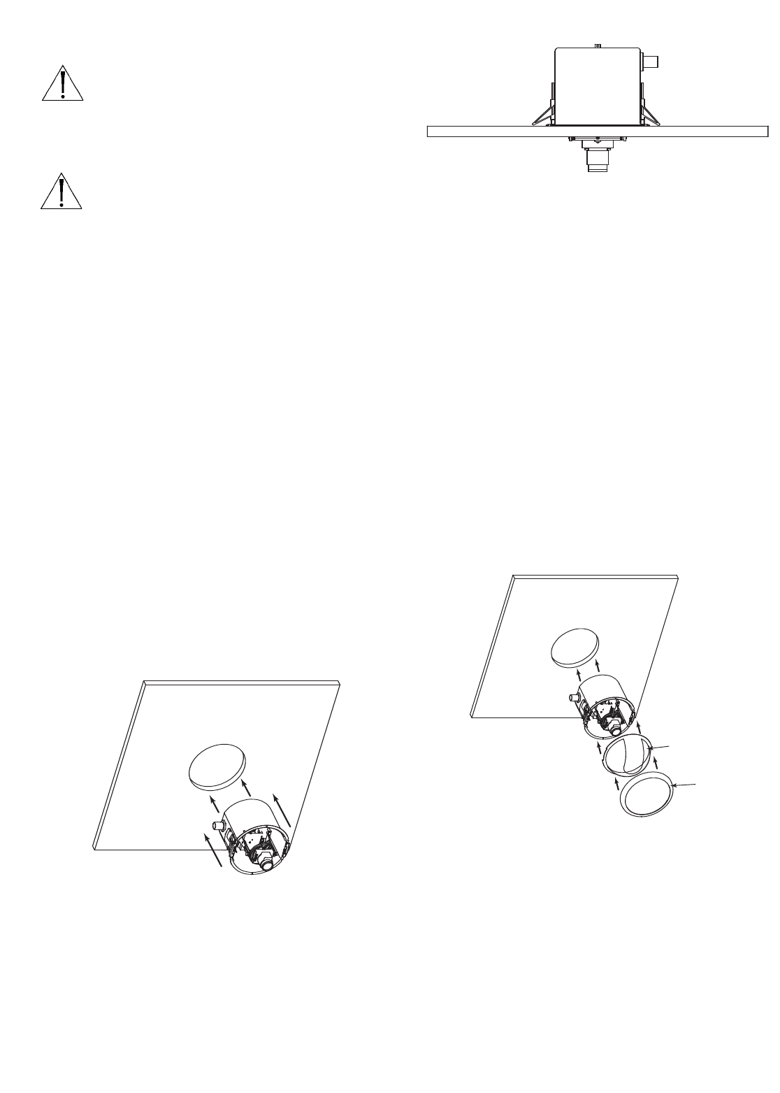
4. Install box into pre-cut tile. Position the round section of
the box in the direction that the camera will be aimed
(see
Figure 1).
Figure 1
5. Pull the drawstring tight (away from the screw) to clamp
down on the ceiling, then lock the drawstring into the
groove. Figure 2 shows the housing clamped to the ceiling.
DO NOT CUT DRAWSTRING. Push the excess string
through the hole provided.As an option, a screwdriver may
be used to turn screws and lock ceiling clamps in place.
Figur
e 2
6. Reinstall tile in grid.
7. Fasten support wire (not provided) to structural framing,
masonry, or concrete above the unit. Connect the other
end to the eyebolt in the top of the box. Draw wire tight
and twist securely.
8. Adjust camera for proper viewing angle.
9. Assemble dome in the trim ring by lining the slots in the
dome with tabs in the trim ring and pushing the sides of the
dome under the tab.Turn the dome to secure it
(see
Figure 3).
10. Attach the dome/trim ring by lining up the dots on the
box and the trim ring. Push on one side of the trim ring
near the flat section of the box, then push on the other
side of the trim ring until it snaps into place. Listen for a
distinct click to ensure ring is securely in place
(see Figure 3).
Figur
e 3
Dome
Tri m Ring
5 INSTALLATION
Attention: Installation should be performed by
qualified service personnel only, in accordance
with the National Electrical Code or applica-
b
le local codes. Refer to applicable installation
section.
5.1
Suspended Ceiling Mounting
CAUTION:These units must be properly and
secur
ely mounted to a supporting structure
capable of sustaining the unit weight. Use care
when selecting mounting hardware (not sup-
plied) for installation.The mounting surface and
unit's weight should be carefully considered.
11. Adjust the dome so that the viewing slot is in the proper
position.
5.2 Hard Ceiling Mounting
Mount the unit in a har
d ceiling,
e.g. dry wall etc. as follows. Be
sur
e the ceiling will suppor
t the w
eight of the housing and
camera.
(continued on back cover)


