


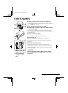
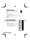
PARTS NAMES
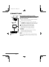
1 Video output connector (VIDEO OUT: BNC type)
Connect this connector to a device such as a VCR or monitor
with a VIDEO IN connector.
2 12 V DC input terminal (12 V DC, GND)
3 External sync composite video signal input connector
(VS IN: BNC type)
Connect to this connector the synchronizing signal output
from a synchronizing signal device or the composite signal of
a video distributor.
4 Power indicator (POWER)
Comes on when the power to the camera is on.
5 Lens mount cap
The cap is installed to protect the lens mount section.
Remove the lens mount cap before installing a lens (sold
separately).
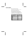
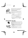
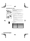
6 Camera installation bracket
The bracket can be fixed at the top or bottom of the
camera. When fixing the bracket, be sure to use the longer
screws and install the shorter screws on the opposite side to
seal the openings.
CAUTION:
When installing the camera support, select a location
that can support the total weight of the camera and
accessories.
1
2
3
2
1
6
5
1
2
4
3
1 Shorter screws: M3 x 4
2 Longer screws: M3 x 6
3 Camera mounting
screw hole: 1/4"-20
UNC
L72K2/US2 GB 1998, 2, 24
4 English