


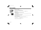
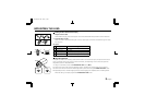

PARTS NAMES
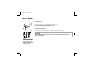
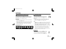
1 Power indicator (POWER)
Comes on when the power to the camera is on.
2 Video output connector (VIDEO OUT: BNC type)
Connect this connector to a device such as a VCR or monitor with a VIDEO IN connector.
3 AC power cord
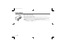
4 External sync composite video signal input connector
(VBS IN: BNC type)
Connect to this connector the synchronizing signal output from a synchronizing signal device or the composite
signal of a video distributor.
5 Line phase adjustment volume (LINE PHASE)
When using two cameras or more, the image on the monitor may roll vertically when switching sources. This
rolling can be minimized by turning this volume.
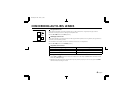
6 Y/C OUT connector (4 pin)
Separate Y (luminance) and C (chroma) signals are output from this terminal.
A better picture quality is obtained if the monitor or VCR is connected to this connector.
1 Y signal ground 2 C signal ground
3 Y signal: 1.0 Vp-p, 75 ohms, unbalanced, negative sync
4 C signal: 0.3 Vp-p, 75 ohms, unbalanced
1
3
2
5
4
6
12
43
L53T5/XE GB 2001, 7, 26
English 3