


5
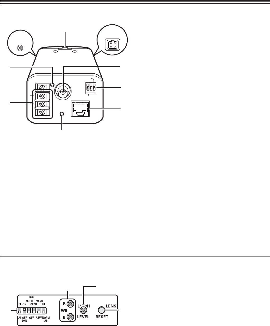
Parts Names and Functions
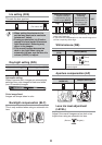
Rear
POWER VIDEO OUT
LAN
LINK
CLASS 2 WIRING
GND
AC24V
--
DC12V
--
ALARM OUT
ALARM IN
COM
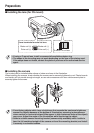
Flange back fixing screw
Flange back adjustment lever
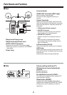
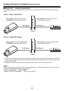
AC24V / DC12V terminals
Connect this terminal to the power supply.
When the camera is turned on, the POWER
lamp lights.
Power lamp
■
•
Lens terminals
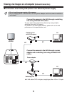
VIDEO OUT connector (BNC type)
Used to output image signals.
Connect to video equipment such as a
monitor.
Control terminals
When connecting the cable, press and hold
down the protrusion of the terminal, insert the
cable into the terminal, and then release the
protrusion.
COM terminal (Earth terminal)
ALARM IN terminal
Connect to a device such as an external
alarm switch or an infrared sensor.
ALARM OUT terminal
Used to connect to an external buzzer or
lamp.
When an alarm is detected, the device
connected to the terminal notifies that an
alarm is detected.
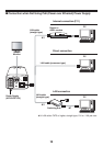
LAN connector (RJ-45)
Used to connect the camera to your network.
LINK lamp
When connected correctly to the network, the
lamp will illuminate 3 seconds after the power
is turned on.
Flashes while data is being transferred.
•
•
•
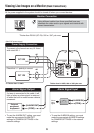
Side■
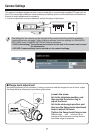
Camera setting switches (P7)
White balance manual adjustment
controls
R: Red adjustment
B: Blue adjustment
Iris adjustment control (LEVEL)
This can only be adjusted when using a DC-
type automatic iris lens.
Reset button (RESET)
If pressed for approximately 5 seconds, it
initializes the various NETWORK SETTINGS
settings (such as IP address) for network
operations.