


Time
Lx
B/W
mode
B/W
mode
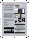
Color mode IR cut filter ON
Proprietary auto-switching
infrared cut filter
Switchover point
B/W mode
(Approx.)
High mode
1~3 lx
3~9 lx
Low mode
Color mode
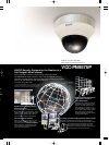
Intelligent Switching from Color to B/W
Switching between color mode during daylight hours and
monochrome at night is done automatically (manual switching
also possible). Selection of switching settings can be made
from a range of 1 to 10 lx.
(F1.9, 20 IRE)
(F1.9, 50 IRE)
B/W mode
0.024 lx
0.06 lx
Color mode
0.48 lx
1.2 lx
Gain: HighGain: High
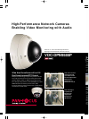
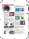
Installation, Setup and Operation Made Easy by
Simple, User-Friendly Design
Based on a development concept featuring a pan-focus lens for
the realization of advanced surveillance functions together with
enhanced operability and ease of installation. The VDC-DPN9585P
and VCC-PN9575P increase lens function and camera maneuver-
ability to simplify operation, save resources spent in installation
and substantially heighten the available degree of freedom.
Tough Die-Cast Aluminum with
Polycarbonate Dome
Housed in an exceptionally tough die-cast
aluminum enclosure and a polycarbonate
dome for extra durability under the most demanding of condi-
tions. To protect against tampering, the screws of the enclo-
sure cover have a unique shape that prevents it from being
opened with ordinary tools.
IP66 Rated Weatherproof Design
Easy Interior Access and Setup
Inside the housings of the VDC-DPN9585P and VCC-PN9575P
are camera units with integrated motors and lenses. Installation
on ceilings or walls can be accomplished without difficulty and
components such as the camera unit or an optional heater
board* can be attached and detached easily in just a few steps.
*The heater board option can be mounted only in the VDC-DPN9585P.
High Sensitivity,
Minimum Required
Illumination
Functions Specific to the
VDC-DPN9585P
User-Friendly Design and Easy Setup
VDC-DPN9585P/VCC-PN9575P
for
nts
E,
-
4-
ble
d to
ord.
re
ec-
the
ts
tion
Bottom
cover
Base
plate
Ceilling mounting
Wall mounting
Push
Ceiling suspension bracket
VA-50BPL VA-50BPS
Wall mounting bracket
VA-50BW
Attachment
VA-50AL
(for VDC-DPN9585P)
Attachment
VA-50AS (for VCC-PN9575P)
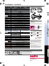
Mounting Brackets (Options)
[Unit: mm (inch)]
Attachment + Brackets
VA-50AL + VA-50BW
VA-50AL + VA-50BPL
VA-50AL + VA-50BPS
VA-50AS + VA-50BW
VA-50AS + VA-50BPL
VA-50AS + VA-50BPS
Model name
VDC-DPN9585P
VCC-PN9575P
Installation
Wall mounting
Long ceiling mounting
Short ceiling mounting
Wall mounting
Long ceiling mounting
Short ceiling mounting
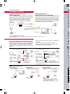
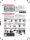
Mounting and Installation
In the case of the VCC-PN9575P
The product pictured below is the VDC-DPN9585P. Specifications differ slightly in the case of the VCC-PN9575P.
Please refer to the operating instructions supplied with each product for details.
The camera unit and board
can be attached or detached
by simply sliding the stopper.
Hold down the button on the side of the housing and
detach the base plate from the back of the camera.
Set up and adjust according
to the installation site.
Installation is completed by simply
attaching the camera to the base plate.
Attach the camera unit to the bottom
cover mounted at the surveillance
point (ceiling or wall).
Set up and adjust according to the installation site.
Note: In the case of a wall mounted setup, hold down the clamp and
release the hooks, then lift the camera unit and turn it 90° to attach it.
66.7
(2.63)
209 (8.23)
M6 *6-2
M24 *P-1.5
205 (8.07)
6 (0.24)
6 (0.24)
83.5 (3.29)
ø120 (4.72)
209 (8.23)
M24 *P-1.5
M6 *6-2
Minimum Length
440 ±3 (17.32 ±0.12)
6 (0.24)
ø120 (4.72)
Maximum Length
1020 ±6 (40.16 ±0.24)
6 (0.24)
83.5 (3.29)
ø7–4 (0.28–0.16)
ø120 (4.72)
66.7
(2.63)
ø120 (4.72)
Maximum Length
464 ±6 (18.27 ±0.24)
M24 *P-1.5
M6 *6-2
Minimum Length
300 ±3 (11.81 ±0.12)
66.7
(2.63)
83.5 (3.29)
ø7–4 (0.28–0.16)
ø120 (4.72)
6 (0.24)
6 (0.24)
0.5
(0.02)
4.5 (0.18)
22.4 (0.88)
41.7 (1.64)
83.4
(3.28)
45.5
(1.79)
ø150 (5.91)
22.8
(0.90)
22.8
(0.90)
82.5
(3.25)
46.0
(1.81)
<M25 15>
R18.7 (0.74)
R151.9
(5.98)
R154.9
(6.10)
93°
0.3 (0.01)
167.3 (6.59)
162.8 (6.41)
22.4 (0.88)
8.0 (0.31)
42.0
(1.65)
3.4 (0.13)
M4 8 4
Note: Attachments and brackets presented are for indoor use.
In cases of outdoor use, measures must be implemented to ensure waterproofing.