


3. The terminal block provided on /x0 units accepts wire
ranging from 20 to 14 AWG or 1.5 mm
2
. The terminal
block provided on /x1 units accepts wire ranging from 18
to 12 AWG or 2.5 mm
2
. When using larger wire sizes,
splice to a smaller size wire at the terminal block end.
The splice may need to be enclosed in a junction box if it
does not pass through the fittings.
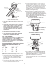
4. A screw/terminal lug is provided for securing a safety
ground. To attach the safety grounding wire (green 115
volt, green/yellow 230 volt), first unscrew the terminal lug
and strip and crimp the grounding wire into the lug.
Attach the terminal lug to the bracket using the M4 x 10
screw provided. See Figure 8.
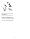
Figure 8: Power Connections - Nonfan Units
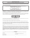
Figure 9: Power Connections - Fan Units
5. Pull any excess wire out of the housing and tighten the
fitting to 8.5 N
.
m to 9.0 N
.
m (75 in
.
lb to 80 in
.
lb). This
torque rating is approximately 1 to 1-1/2 turns past the
point where the fitting starts to grip the wire.
Failure to do so will allow water to enter and damage all
electronic parts.
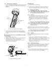
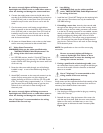
Figure 7: Feed-through Wiring
2. Screw the two 3/8-inch NPT fittings into the foot of the
housing.
3. Pull the cabling through the fittings and into the housing.
Tighten the fitting to 4.0 N
.
m to 4.5 N
.
m (35 in
.
lb to
40 in
.
lb). This torque rating is approximately 1 to 1-1/2
turns past the point where the fitting starts to grip the
wire. Failure to do so will result in water damage to all
electronic parts.
4. Attach the foot to the top bracket of the mount.
5. Cover the holes in the rear cap with the rubber plugs
provided. Push in until flush and then release.
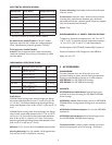
6.6.4 Power Connections
Power connection into the housings is to be supplied through
a minimum type UL Standard "SJ" cord acceptable for
outdoor use. Installation must conform to acceptable NEC
and local codes. For 24 volt cameras, use the chart below for
selecting the proper wire size.
Recommended Maximum Cable Lengths for Housings
Equipped with 24 Volt Cameras, Heaters, and
Blowers
Wire Size Housing Distance
mm
2
AWG meters feet
0.5 20 28.6 94
118 45.7 150
1.5 16 70.1 230
2.5 14 115.5 379
412 183.8 603
610 292.6 960
10 8 464.2 1523
NOTE: The use of wire sizes larger than 1.5 mm
2
(14 AWG) will require a
splice in order to accomodate the terminal block.
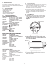
1. Install one of the large 1/2-inch NPT fittings into one of
the holes in the rear cap. The terminal block side is
preferable. If you are using the feed-through option,
ignore this step.
2. Route the power cable through the fitting in the rear cap
or one of the feed-through fittings in the foot.
8
Remove These
Dome Plugs
3/8-inch NPT
Fitting
Foot
1/2-inch
Rubber Plugs
Rear Cap
Fuseholder
Terminal Lug
(LTC 9480/00 only)
M4 Nut (Use a
7 mm wrench)
Line
Neutral
Ground
Terminal
Lug
Screw
Ground
Neutral
Line
Terminal Lug
Screw
Fuseholder