


6.8 Lens Wiring
WARNING: Only use the cables specified
under "INSTALLATION, Cable Requirements"
for wiring of the lens.
1. Install the last 1/2-inch NPT fitting into the remaining hole
in the rear cap. Zoom lenses can only be installed into
VSE-2400 housings.
2. If installing a zoom lens, insert the lens control cable
through the last fitting at the rear of the housing. Attach
the lens wiring to the lens mating connector and connect
it to the lens. If mating connector is not available, connect
directly to the lens cable. Pull any excess wire out of the
housing and tighten the fitting to 8.5 N
.
m to 9.0 N
.
m
(75 in
.
lb to 80 in
.
lb). This torque rating is approximately 1
to 1-1/2 turns past the point where the fitting starts to
grip the wire. Failure to do so will result in water damage
to all electronic parts.
NOTE: See specification on lens cord for correct plug
connection.
Be sure to securely tighten all fittings to
ensure a liquid-tight seal. Failure to do so
could allow water to enter the housing and
damage the camera and lens.
3. If using a pan/tilt with a feed-through cable, insert
the camera/lens function cable in through the left fitting at
the rear of the cradle. Wire the functions as described
above or as needed.
Use of "drip loops" is recommended on the
wiring outside of the rear end cap.
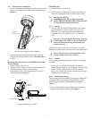
6.9 Camera/Lens Adjustment
Verify camera and lens operation before final assembly of the
cradle into the housing. Adjust the camera focus and iris as
necessary. See individual camera instructions.
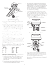
6.10 Final Assembly
1. Use the plugs or fittings provided to plug any remaining
holes in the rear cap.
2. Reinstall the cover. Align the bottom of the cover ribs
with the top of the base. Slide the cover onto the base.
Make sure the seal is not folded over or torn. Use
silicone grease to lubricate the seals if necessary. See
Figure 10.
Be sure to securely tighten all fittings to ensure a
liquid-tight seal. Failure to do so could allow water to
enter the housing and damage the camera and lens.
6. Connect the supply power wires to the left side or the
top side of the terminal block provided. Strip no less than
6 mm (0.25-inch) and no more than 8 mm (0.31-inch) of
insulation away from the wire. Be sure not to nick the
wires.
7. Cut the camera power cord, leaving enough cable to
allow connection to the terminal block. Strip no less than
6 mm (0.25-inch) and no more than 8 mm (0.31-inch) of
insulation away from the wire. Be sure not to nick the
wires. Connect these wires to the left side or the top
side of the terminal block.
8. On heater and heater/blower units, make sure the heater
and fan wires stay connected to the terminal block.
6.7 Video Coax Connection
WARNING: Only use the cables specified under
"INSTALLATION, Cable Requirements" for
wiring of the video coax connection.
1. For VSE-2300 versions, install a 1/2-inch NPT fitting into
the remaining hole in the rear cap. For VSE-2400 versions,
install a 3/8-inch NPT fitting through the center small hole
of the rear cap.
2. Route the video coax cable through one of the fittings
installed in step 1 or one of the feed-through fittings in
the base.
3. Attach BNC connector to the coax and connect it to the
camera. Pull any excess wire out of the housing and
tighten the fitting to 8.5 N
.
m to 9.0 N
.
m (75 in
.
lb to 80
in
.
lb). This torque rating is approximately 1 to 1-1/2 turns
past the point where the fitting starts to grip the wire.
Failure to do so will result in water damage to all
electronic parts.
Be sure to securely tighten all fittings to ensure a
liquid-tight seal. Failure to do so could allow water to
enter the housing and damage the camera and lens.
Use of "drip loops" is recommended on the wiring
outside of the rear end cap.
9