


56 Cheetah 10K.6 FC Product Manual, Rev. B
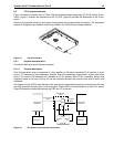
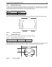
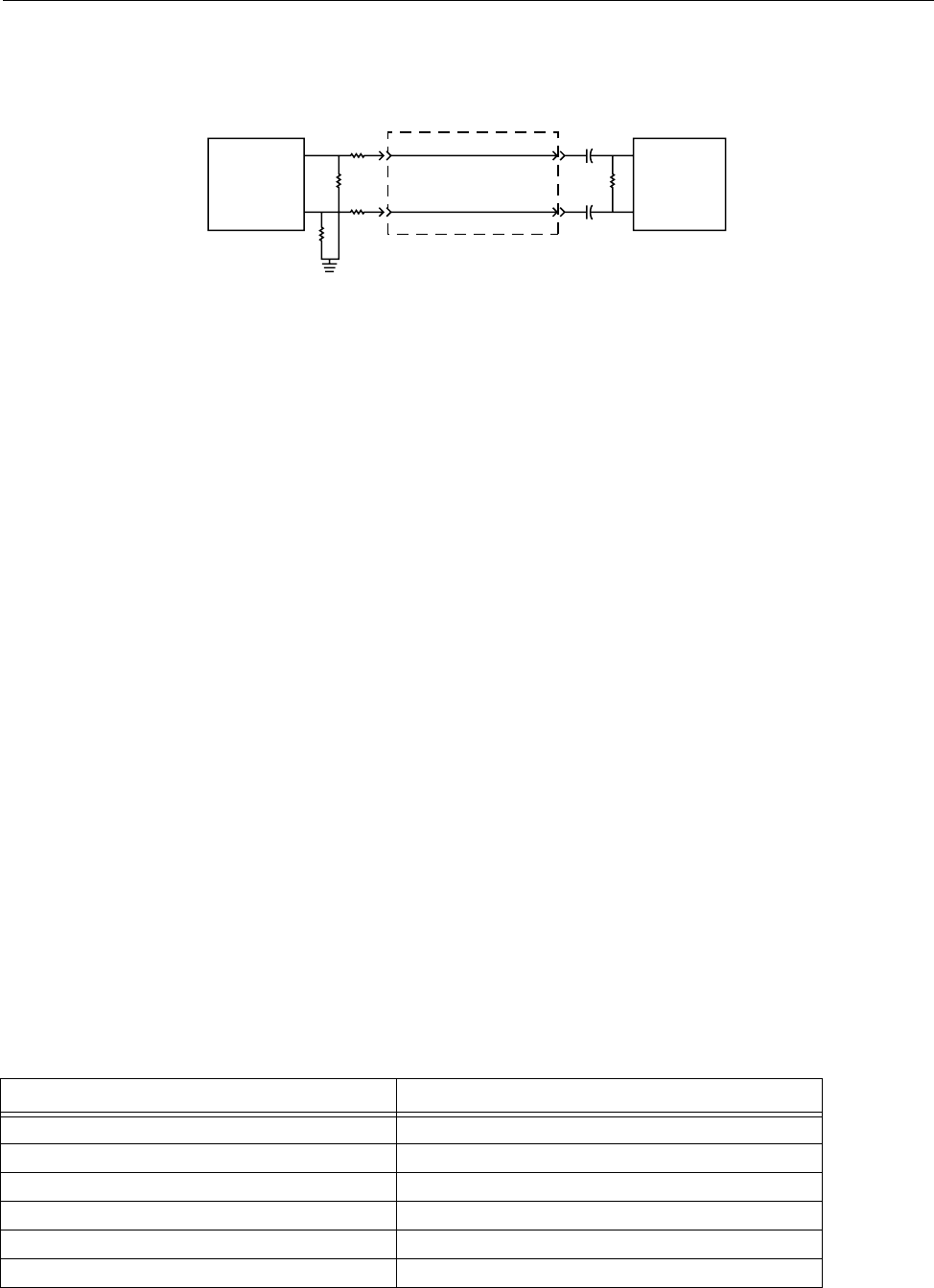
9.5.5 FC-AL transmitters and receivers
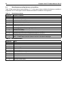
A typical FC-AL differential copper transmitter and receiver pair is shown in Figure 23. The receiver is required
to provide the AC coupling to eliminate ground shift noise.
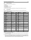
Figure 23. FC-AL transmitters and receivers
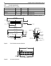
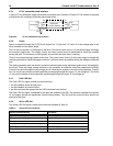
9.5.6 Power
Power is supplied through the FC-SCA with support for +5 volts and +12 volts. All of the voltage pins in the
drive connector are the same length.
Four 12 volt pins provide +12 volt power to the drive. The current return for the +12 volt power supply is through
the common ground pins. The supply current and return current must be distributed as evenly as possible
among the pins. The maximum current typically occurs while the drive motor is starting.
Three 5 volt pins provide logic power to the drive. The current return for the +5 volt power supply is through the
common ground pins. Distribute supply and return current as evenly as possible among the voltage and ground
pins.
The mating connector pins use shorter contacts to achieve power surge reductions and to aid in “hot plugging”
the drives. There are longer voltage contacts in the connector to enable the drive filter capacitors to charge.
Current to the drive through the long charge pins is limited by the system in which the drive operates. Three of
the +12 volt pins are shorter to allow capacitive pre-charging through the longer +12 volt charge pin. Two of the
+5 volt pins are shorter to allow capacitive precharging through the longer +5 volt charge pin.
9.5.7 Fault LED Out
The Fault LED Out signal is driven by the drive when:
• the drive detects failure of both ports
• the drive detects an internal failure
• the drive receives the appropriate fault LED command from the host
The Fault LED Out signal is designed to pull down the cathode of an LED. The anode is attached to the proper
+5 volt supply through an appropriate current-limiting resistor. The LED and the current-limiting resistor are
external to the drive.
9.5.8 Active LED Out
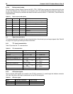
The Active LED Out signal is driven by the drive as indicated in Table 21.
Table 21: Active LED Out conditions
Normal command activity LED status
Spun down and no activity Slow blink (20% on and 80% off a 2 sec cycle)
Spun down and activity (command executing) On
Spun up and no activity On
Spun up and activity (command executing) Off
Spinning up or down Blinks steadily (50% on and 50% off)
Format in progress, each cylinder change Toggles on/off
TY
150
68
68
.01
150
Differential
Transfer Medium
.01
150
Transmitter
TX
RY
Receiver
RX