3.1.16.2 FROG Data Orientation
The FROG software has the ability to flip axial assignments and directions. There is, however, a
legacy defined orientation that we use as a basis for defining our axial representations. This is
also the FROG default condition.
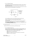
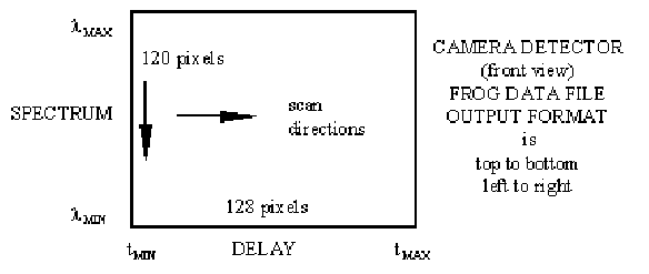
Looking into the front of the camera, the upper left corner defines a starting point for the vertical
Spectrum axis and then the horizontal Delay axis. (See figure below).
Figure 12
In the vertical/Spectrum direction, the top represents a maximum wavelength (lowest
frequency), moving down to a minimum wavelength (highest frequency).
In the horizontal/Delay direction, the left represents a minimum time delay moving right to a
maximum time delay.
If you align your axes differently than shown, you can make the necessary adjustments by
altering the Delay and Wavelength settings in the dialog box and in the Exp. Data tab section
of the FROG Algorithm Calibration dialog box.
Note: The LBA-PC always builds the .frg data file in the format depicted above, listing the columns top to bottom
then stepping from left to right.
Reference the FROG on-line Help for details on the FROG data file format.
3.1.16.3 FROG Data Collection Tips
Most of the LBA-PC data collection features are not required when collecting FROG data. Thus,
the Results child window can be minimized, which will speed up data collection. The following
list contains some Do’s and Don’ts for reducing errors when collecting FROG data:
• DO use Ultracal! just prior to starting a data collection cycle.
• DON’T enable Lens in the Camera dialog box.
• DO save your configuration when the camera is aligned with your spectrometer.
• DON’T drive the camera into saturation.
Operator’s Manual LBA-PC
Doc. No. 10654-001, Rev 4.10
47


