


Chapter 1 Overview
28 Chapter 1 Overview
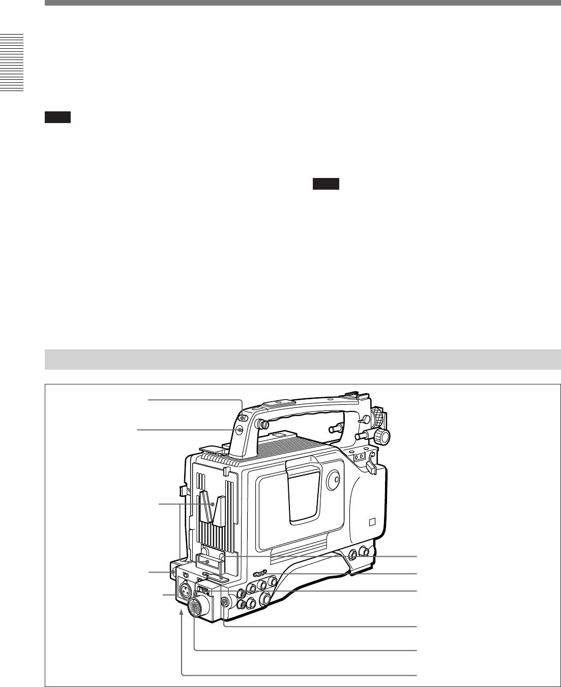
Location and Function of Parts
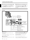
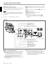
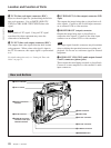
Rear and Bottom
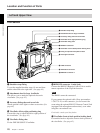
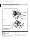
6 WRR connector
7 Cable clamp
8 DV OUT connector
9 DC OUT connector
0 VTR/CCU connector
qa BREAKER button
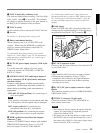
3 TC IN (time code input) connector (BNC)
Input an external signal for synchronizing the built-in
time code generator. Use an SMPTE (DSR-370/
570WS) or EBU (DSR-370P/570WSP) time code
signal.
Note
Use a jitterless LTC signal. Using an LTC signal
reproduced by other equipment may cause the
camcorder to malfunction.
4 TC OUT (time code output) connector (BNC)
This outputs time code signals from the built-in time
code generator. When a time code signal is input to
the TC IN connector, this output signal is synchronized
to it.
For details about time code, see “Setting the Time code
Value” on page 73.
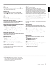
5 S VIDEO OUT (S-video output) connector (DIN
4-pin)
This outputs the image being shot or played back as S-
video signals. Connect to the S-video input connector
on an external VCR or video monitor.
6 MONITOR OUT (output) connector
Outputs the image being shot or played back as
composite video signals. Connect to the video input
connector on an external VCR or video monitor.
Note
The output signal from this connector may discontinue
when switching the operation between recording and
playback. Do not use as a reference signal for external
equipment.
7 AUDIO OUT CH-1/CH-2 (audio output channel
1 and 2) connectors (phono jacks)
These output the sound being recorded or played back.
Connect to a stereo amplifier or video monitor’s audio
input connectors.
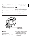
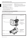
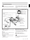
1 TALLY indicator
2 TALLY switch
3 Battery attachment
interface
4 DC IN connector
5 AUDIO IN CH-1/CH-2
connectors and input
selection switches