


3
VISCA
1)
RS-232C/RS-
422 Commands
Use of RS-232C/RS-422 control software based upon
this command list may cause malfunction or damage to
hardware and software. Sony Corporation is not liable
for any such damage.
Overview of VISCA
In VISCA, the side outputting commands, for example,
a computer, is called the controller, while the side
receiving the commands, such as a BRC-Z330, is called
the peripheral device. The BRC-Z330 serves as a
peripheral device in VISCA. In VISCA, up to seven
peripheral devices like the BRC-Z330 can be connected
to one controller using communication conforming to
the RS-232C/RS-422 standard. The parameters of RS-
232C/RS-422 are as follows.
• Communication speed: 9600 bps/38400 bps
• Data bits : 8
• Start bit : 1
• Stop bit : 1
• Non parity
Flow control using XON/XOFF and RTS/CTS, etc., is
not supported.
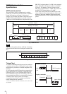
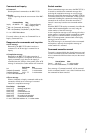
Peripheral devices are connected in a daisy chain. As
shown in Fig. 1, the actual internal connection is a one-
direction ring, so that messages return to the controller
via the peripheral devices. The devices on the network
are assigned addresses.
The address of the controller is fixed at 0.
The addresses of peripheral devices are as follows.
When the camera address selector is set to 0
(automatic setting mode)
The peripheral devices are assigned to the addresses, 1,
2, 3… in the connected order, starting from the one
connected nearest to the controller. These addresses are
set when the controller sends address commands during
initialization of the network.
When the camera address selector is set to 1
through 7 (manual setting mode)
The addresses of the peripheral devices will be set to the
pre-selected numbers. Within a single system, the same
number can be used only once. If an address selector
number other than 0 is used, set the camera address
selectors on the connected BRC-Z330 cameras to
different numbers.
Note
In the same network, all the camera address selectors
should be set to “0” (automatic setting) or all the
selectors should be manually set to “1” to “7”. Do not
mix the automatic and manual settings.
Each VISCA equipment has VISCA IN and VISCA
OUT connectors.
Set the DTR input (the S output of the controller) of
VISCA IN to H when controlling VISCA equipment
from the controller.
Fig. 1 VISCA network configuration
VISCA Equipment
IN
OUT
IN
OUT
IN
OUT
VISCA Controller
............................................................................................................................................................................................................................
1) VISCA is a protocol developed by Sony for controlling a consumer’s camcorder. “VISCA” is a trademark of Sony Corporation.