


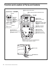

Function and Location of Parts and Controls
7
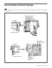
a TALLY lamp and TALLY switch
When the TALLY switch is ON, the TALLY lamp lights
when a red tally signal, green tally signal, or call signal is
input from the CCU.
Turning the S101 switch on the internal AU-294 board to
ON mixes and outputs the battery alarm signal to the
TALLY lamp.
b RET 1 button, RET button and RET 2/3/4 switch
RET1 (return video 1) button
While this button is pressed down, the return video1 signal
from the CCU (camera control unit) can be monitored in
the viewfinder or on a monitor connected to the RETURN
connector.
RET (return video) button
While this button is pressed down, the return video signal
from the CCU can be monitored in the viewfinder. Select
the monitored signal with the RET 2/3/4 switch.
RET 2/3/4 switch
Selects the return video signal to be monitored in the
viewfinder while the RET button is pressed down.
c LIGHT switch
Turns the backlight on the upper part of the panel and the
light on the connector section on or off. Depending on the
switch position, both lights turn on, only the light on the
connector section turns on, or both lights turn off.
d PGM (program audio) 1/2 level controls (for the
CA-590)
These controls adjust the audio volume of the program.
PGM level controls are provided for both intercom 1 and 2.
e Triax connector
Connects a CCU-550D/550DP/590/590P/700A/700AP/
790/790P Camera Control Unit through a triax cable.
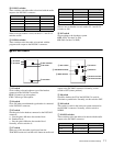
f INCOM level controls, PROD/ENG switches, and
MIC LEVEL switches (for the CA-590)
INCOM (intercom) level controls
These controls adjust the audio reception level of the
intercom 1/2.
PROD/ENG (producer/engineer) switches
Select the line for the microphone of the intercoms
connected to the respective INCOM connectors.
PROD: Selects the producer’s line.
ENG: Selects the engineer’s line.
MIC/LEVEL (microphone/intercom level) switches
The MIC and LEVEL settings specify the following
functions:
ON/REAR: Turns on the intercom microphone. Adjust
the intercom reception level with the INCOM level
control.
OFF/REAR: Turns off the intercom microphone. Turn
the intercom microphone on and off using the control
on the external equipment connected to the RET
CTRL connector. Adjust the intercom reception level
with the INCOM level control.
OFF/FRONT: Turns off the intercom microphone. Turn
the intercom microphone on and off using the control
on the external equipment connected to the RET
CTRL connector or the VTR S/S switch on the video
camera. Use the control on the video camera to adjust
the intercom reception level. Depending on the video
camera, intercom reception level adjustment requires
menu operation.
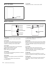
g INCOM (intercom) 1/2 connectos
Connect headsets to enable the reception of program/
intercom audio and transmission of intercom audio.
Set the S3 switch on the internal MA-128 board to “CM”
when using headsets with a carbon-type microphone, and
set it to “DYN” when using headsets with a dynamic-type
microphone.
The INCOM 1 connector can be used for communications
through the engineer’s line even though the power to the
camera is turned off on the CCU-550D/550DP/590/590P/
700A/700AP/790/790P.
h TRACKER connector (10-pin)
Used for communications with a tracker and intercom 1
and 2 communications. Also outputs the up tally and
program audio signals. The maximam current output from
this connector is 500 mA. Settings regarding the input/
output signals can be made on the internal AU-294 board.
i DC IN (direct current input) connector (4-pin)
Connects an AC adapter or battery case. Supplies power
to the CA-590/590P when the POWER switch is set to
EXT.
j RETURN (return video output) connector (BNC
type)
Outputs the return video signal.
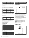
k PROMPTER (prompter video signal input/output)
connector (BNC type)
Inputs and outputs a prompter video signal. Use the S301
switch on the DM-139 internal board to select the
transmission direction (input or output) of the prompter
video signal. When the setting is made on the camera
adaptor, the transmission direction must be also changed
on the CCU.
l DC OUT (direct current output) connector (4-pin)
Outputs a direct current of 10.5 V to 17 V at a maximum
rated current output of 1.5 A. Connecting equipment with
a power consumption greater than the maximum rating
will activate the protection circuit, cutting off the current
flow.