


15
Location and Functions of Parts
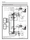
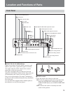
Front Panel
TALLY/FAN ALARM
PANEL
ACTIVE
LOCK
INTERCOM
ON
CALL GAIN DETAIL KNEEMASTER
GAMMA
CAMERA
SHUTTER SPEED/CABLE LENGTH
BARS
HIGH
AUTO
MID
LOW
SHUTTER
OFF
CLEAR SCAN
AUTO
BLACK WHITE ATW
H
PRESET
RBLACK B
MANUAL
OFF
POWER
1
CAMERA CONTROL UNIT CCU-D50
IRIS
MASTER
BLACK
AUTO
RWHITE B
I
SC
MENU
SELECT FINE
DIGITAL
TRANSMISSION
Y
C
ENTER
CANCEL
SELECT
OUTPUT SHUTTER
WHITE/BLACK BALANCE PHASE
MENU
CABLE COMP
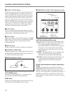
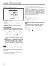
1 TALLY/FAN ALARM indicator
2 LOCK switch
3 PANEL ACTIVE button
4 CALL button
5 GAIN switch
6 DETAIL knob
7 MASTER
GAMMA knob
8 KNEE
adjustment
section
9 WHITE/BLACK BALANCE adjustment section
q; PHASE adjustment section
qa CABLE COMP adjustment section
qs DIGITAL TRANSMISSION indicator
qd AUTO IRIS button
qf IRIS knob
qg MASTER BLACK knob
qh System setting switches
qj Intercom setting switches
qk MENU section
ql SHUTTER adjustment section
w; Mode switch
wa INTERCOM connector and volume knob
ws POWER switch
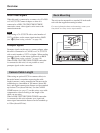
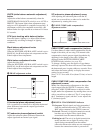
1 TALLY/FAN ALARM indicator
Lights in red when a red tally signal is received, and
lights in green when a green tally signal is received.
Also lights when the CALL button of the camera/
camcorder or this unit is pressed.
This unit is equipped with a cooling fan. If the fan
should fail, this indicator flashes in red. Power the unit
off immediately and contact your Sony dealer or a
Sony service representative for repair. Continuing to
use the unit with a malfunctioning fan may shorten the
life of this unit.
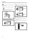
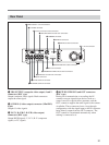
You can attach the supplied camera number plates to
this indicator (see the following figure).
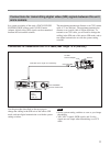
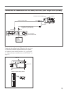
2 LOCK switch
Locks and unlocks the controls on this unit.
ON: Locks all controls on this unit except the CALL
button, the INTERCOM volume knob, and the
CABLE COMP buttons and CABLE COMP FINE
screws.
OFF: Unlocks the controls. Normally leave the
switch in this position.
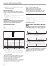
Cover of the setting switches