


21
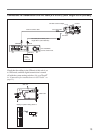
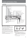
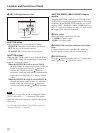
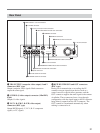
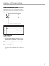
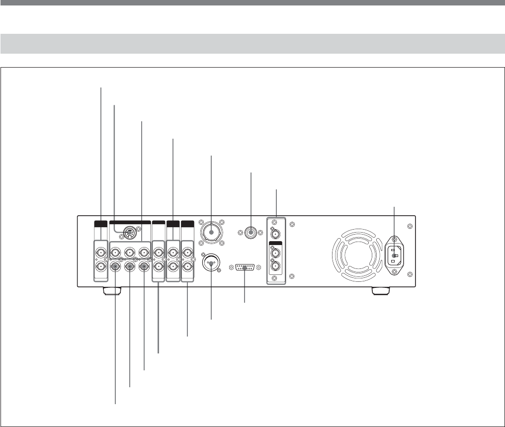
Rear Panel
1
2
Y/G/Y
S VIDEO
MONITOR
OUTPUT
R-Y/R/C
SYNC
OUTPUT
B-Y/B IN
OUT
CAMERA
MIC OUT
INTERCOM/TALLY/AUX
1
2
SDI IN
REMOTE
IN
OUT
IN
OUT
VBS
OUTPUT
GENLOCK
SDI OUT
OUTPUT
RETURN
VIDEO
PROMPTER
VIDEO
1 VBS OUTPUT 1 and 2 connectors
2 S VIDEO connector
3 Y/G/Y, R–Y/R/C, B–Y/B connectors
4 RETURN VIDEO IN and OUT connectors
5 CAMERA connector
6 REMOTE connector
7 SDI IN and OUT connectors
8 - AC IN connector
9 INTERCOM/TALLY/AUX connector
q; MIC OUT connector
qa PROMPTER VIDEO IN and OUT connectors
qs GENLOCK IN and OUT connectors
qd Spare connector
qf SYNC OUTPUT connector
qg MONITOR OUTPUT connector
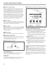
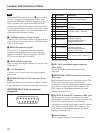
1 VBS OUTPUT (composite video output) 1 and 2
connectors (BNC type)
Output composite video signals. Both connectors
output the same signal.
2 S VIDEO (S-video output) connector (Mini-DIN,
4-pin)
Outputs S-video signals.
3 Y/G/Y, R–Y/R/C, B–Y/B (video output)
connectors (BNC type)
Output R/G/B signals, Y, R–Y, B–Y component
signals, or YC signals.
4 RETURN VIDEO IN and OUT connectors
(BNC type)
During on-air transmission or recording, the IN
connector accepts signals from devices such as a
control console or special effect generator, and the
OUT connector supplies the same signal to the camera
viewfinder. These connectors have a loop-through
configuration, with the signal input to the IN connector
being directly output from the OUT connector. The
OUT connector is terminated automatically when
nothing is connected to it.