102 Chapter 4 Viewfinder Screen Indications and Menus
Chapter 4 Viewfinder Screen Indications and Menus
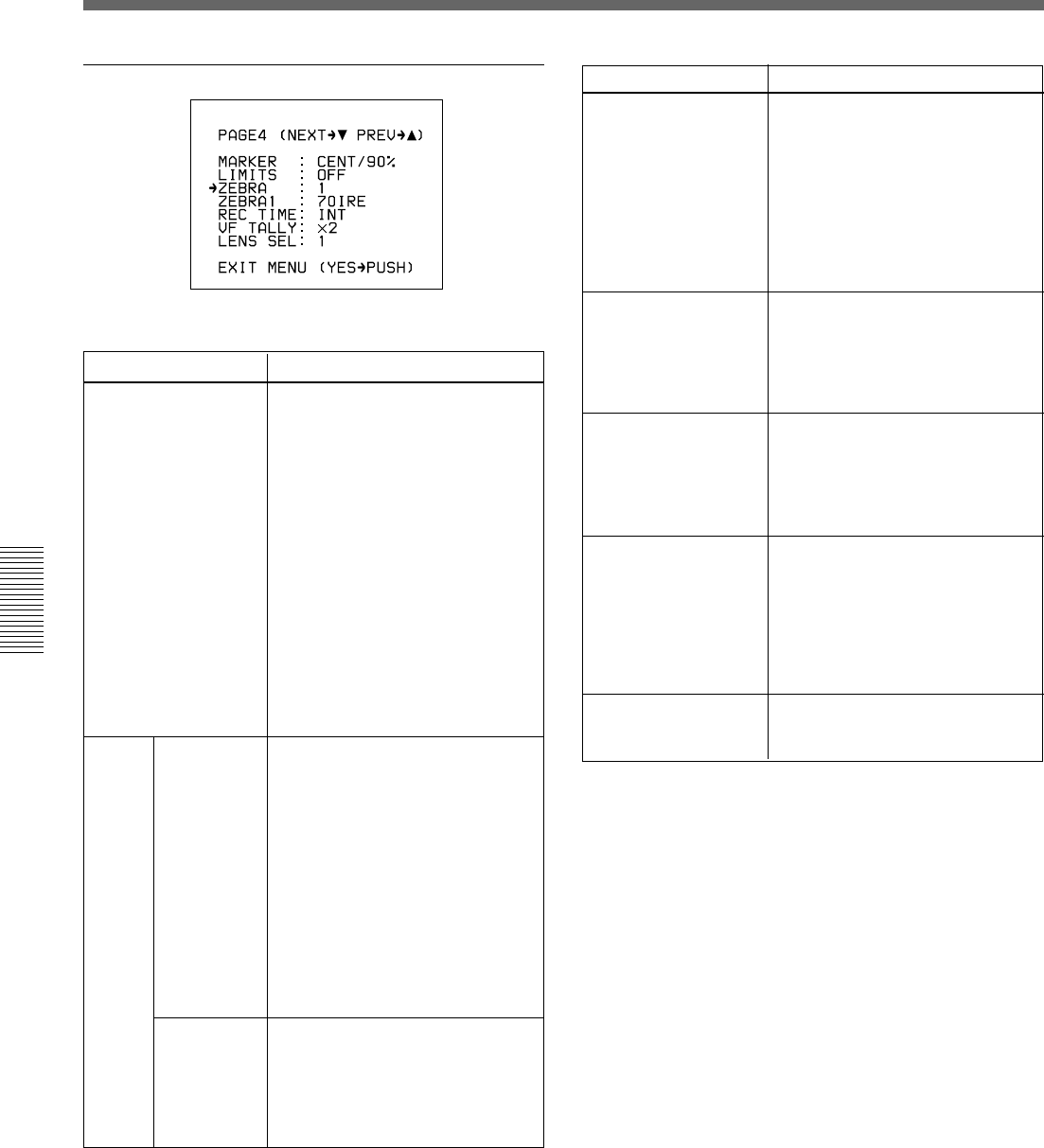
Viewfinder Advanced Menu
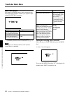
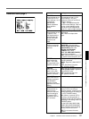
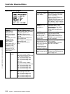
MARKER
Selects ON/OFF
setting for center
marker, size setting,
and display ON/OFF
setting.
The safety zone value
differs as follows,
depending on the
LIMITS setting.
LIMITS set to OFF: %
value with respect to
viewfinder screen
LIMITS set to value
other than OFF: %
value with respect to
LIMITS value
CENT/90% (normal value):
Displays center marker and safety
zone marker at 90% size.
CENT/80%: Displays center
marker and safety zone marker at
80% size.
90%: Displays only safety zone
marker at 90% size.
80%: Displays only safety zone
marker at 80% size.
CENT: Displays only center
marker.
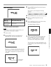
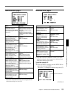
LIMITS
DSR-570WS/
570WSP
Advanced menu page 4
a) For DSR-390P/570WSP: 70%
a)
• 16:9 mode
OFF (normal value): Outputs
safety zone according to scan size.
4:3: 4:3 section safety zone
13:9: 13:9 section safety zone
14:9: 14:9 section safety zone
15:9: 15:9 section safety zone
• 4:3 mode
OFF (normal value): Outputs
safety zone according to scan size.
13:9: 13:9 section safety zone
14:9: 14:9 section safety zone
15:9: 15:9 section safety zone
16:9: 16:9 section safety zone
DSR-390/
390P
OFF (normal value): Outputs safety
zone according to scan size.
13:9: 13:9 section safety zone
14:9: 14:9 section safety zone
15:9: 15:9 section safety zone
16:9: 16:9 section safety zone
Item
Settings
Item
Settings
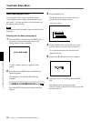
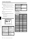
ZEBRA
Selects type of zebra
pattern display.
1 (normal value): Displays the
zebra pattern over parts having a
video level. between 70 and 90
IRE (or 70 and 90%).
Use the next item (ZEBRA1) to
select the base level.
2: Displays the zebra pattern over
parts having video levels of 100
IRE or above (or 100% or above).
1/2: Dual display (both 1 and 2)
70 IRE (normal value) to 90 IRE
(DSR-390/570WS) or 70%
(normal value) to 90% (DSR-
390P/570WSP):
Can be set for each IRE step or
1% step.
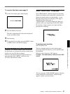
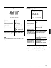
×1: Uses only the upper REC/
TALLY indicator.
×2 (normal value): Uses two
REC/TALLY indicators.
INT (normal value): Recording
time of the internal VCR
EXT: Recording time of the
external VCR connected to the
VTR/CCU connector (26-pin) or
DV OUT connector.
VF TALLY
Selects whether or not
to use more than one
REC/TALLY indicators
in the viewfinder
(displayed only when
the DXF-801/801CE
viewfinder is attached).
ZEBRA1
Sets base level for
zebra pattern 1.
REC TIME
Selects whether to
show the recording
time (TTL) of the
internal VCR or of the
external VCR.
LENS SEL
Select the types of the
lens.
1 (normal value), 2,3,4
For details, see “Designating the
lens” on page 134.


