


1-4
DXC-190
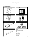
Installation
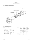
Suitable lenses
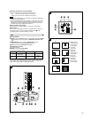
The lens must be either a C- or a CS-mount type of less than 1 kg. The
protrusion behind the mounting surface must be within the following limits:
1 C-mount lens, 2 9 mm or less, 3 CS-mount lens, 4 4 mm or less
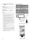
Changing the plug on an auto-iris lens cable
The camera is supplied with a plug to fit the LENS connector. To connect
an auto-iris lens, first replace the plug on the lens cable with the supplied
plug.
1 Detach the old plug from the lens cable.
2 Solder the lens cable to the pins of the supplied plug. (For cable pin
assignment, refer to the instruction manual for the lens.)
1 Cover
2 Lens cable
3 Rib (If the cable is thick, cut this off.)
4 Plug (unit accessory)
5 Pin 4 Video signal control Ground
DC control Ground
6 Pin 2 Video signal control Not used
DC control Control +
7 Pin 1 Video signal control Power supply (DC 9 V, 50 mA)
DC control Control –
8 Pin 3 Video signal control Video signal
DC control Drive +
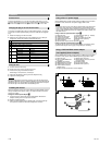
Fitting the lens
1
Unscrew the lens mount cap.
2 Screw in the lens, and turn it until it is secured.
3 Insert the lens plug in the LENS connector.
When fitting a manual-iris lens, omit step 3.
4 Adjust the flangeback by turning the C/CS adjustment ring.
5 Tighten the locking screw.
Caution
When mounting the lens, loosen the securing nut on the side and turn the
flangeback adjustment to the “C” position. Mounting a C-mount lens with the
adjustment ring in the “CS” position may damage the optical filter. Keep the
lens mount cap on the camera when not attaching a lens.
Installing the camera
When mounting the camera on a tripod, attach the tripod adaptor to either
the top or bottom of the camera. Use a 1/4" UNC-20 screw to mount the
camera on a tripod.
Fitting the camera tripod adaptor
G
1 Loosen screws 1–4 that secure the tripod adaptor. Remove the
adaptor carefully, and do not pull at the screws.
2 Remove screws 5 and 6.
3 Attach the tripod adaptor on the opposite side, and insert screws 5
and 6 on the surface from which the adaptor was removed.
F
D
E
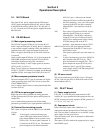
Connections
Using a DC 12 V power supply
Set the MODE switch (mode change switch) to B. When the connections
have been made, set the DC 12 V power supply switch to ON.
Notes
• To prevent short circuits, do not let the exposed ends of the mains lead
wires touch each other when connecting to the mains lead terminals.
• If you use the CMA-D2 camera adaptor (not supplied), you will need the
camera cable CCMC-200/200YC (not supplied). For further details, see
the cable manual.
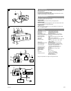
Using an external synchronization signal
H
1 DXC-190 (rear) 7
Synchronization signal (e.g., switcher)
2 VIDEO OUT connector 8 Power supply
3 75-ohm coaxial cable 9 DC 12 V switch (set to ON)
4 VIDEO INPUT connector 0 MODE switch (set to B)
5 VS IN connector qa +12 V
6
Synchronization output connector
qs GND (ground)
Using an internal synchronization signal
H
To operate with an internal synchronization signal, no connection to the
synchronization signal source (5, 6 and 7 above) is necessary.
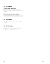
Using a YS-W170/W270 camera adaptor
(not supplied) (Power multiplex)
Set the MODE switch (mode change switch) to A. When the connections
have been made, set the YS-W170/W270 power supply switch to ON.
1 DXC-190 (rear) 7 VIDEO OUT connector
2 DC IN. VS IN/VIDEO OUT 8 VIDEO INPUT connector (monitor
connector input connector)
3 CAMERA IN connector 9 Portable monitor
4 MONITOR OUT connector 0 75-ohm coaxial cable
5 VIDEO INPUT connector qa MODE switch (set to A)
6 YS-W170/W270 camera
adaptor (rear)*
* The figure shows the YS-W170 camera adaptor.
I
D
E
1
2
3
4
1
2
3
4
7
6
5
8