


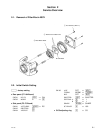


4-5
DXC-190
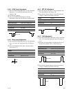
4-4-2. SYNC Level Adjustment
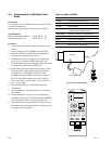
1 Press the STEP FORWARD button on the commander
three times. As a result, the displayed mode will
change to “2B”.
2 Close the lens opening.
3 Press the CHANGE DATA button so that the
determined voltage will fall within the standard range.
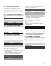
4-4-4. SET UP Adjustment
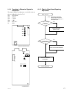
1 Press the step forward button of the commander once.
The mode indicator will display “00”.
2 Press the data change button to ensure the measured
voltage is within the specified value range.
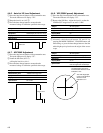
4-4-3. Burst Level Adjustment
1 Press the STEP FORWARD button on the commander
once. As a result, the displayed mode will change to
“2C”.
2 Press the CHANGE DATA button so that the burst
level will be 75 %.
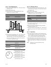
4-4-5. 0 dB Adjustment
1 Press the STEP FORWARD button on the commander
once. As a result, the displayed mode will change to
“5A”.
2 Shoot the all-white pattern, and adjust the lens iris so
that the CCD LEVEL (TP1) is 250 ±20 mV p-p.
3 Press the data change button to ensure the measured
voltage is within the specified value range.
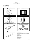
Subject
Measurement point
Equipment
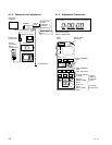
Display Mode
Specification
Lens opening
Free
SYNC level of VIDEO OUT
Waveform Monitor
2B
40 ±4 IRE
Close
Subject
Equipment
Display Mode
Specification
Free
Vectorscope
2C
Burst level is 75 %
All white pattern
Interface Tool TP1 (CCD LEVEL)
Oscilloscope (AC 50 mV, 10 us)
5A
250 ±20 mV
Subject
Measurement point
Equipment
Display Mode
Specification
Close ‘C’
SET UP level of VIDEO OUT
Waveform Monitor
00
7.0 ±2.0 IRE
Subject
Measurement point
Equipment
Display Mode
Specification
All white pattern
Interface Tool TP2 (A/D-IN)
Oscilloscope (AC 200 mV, 10 us)
5A
800 mV
Subject
Measurement point
Equipment
Display Mode
Specification
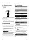
+60
_40
Center
75%
SYNC Level
CCD LEVEL
A/D-IN
SET UP