


10
–
DXC-S500 Product Information Manual
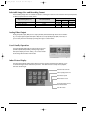
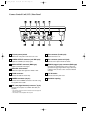
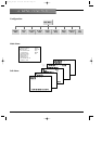
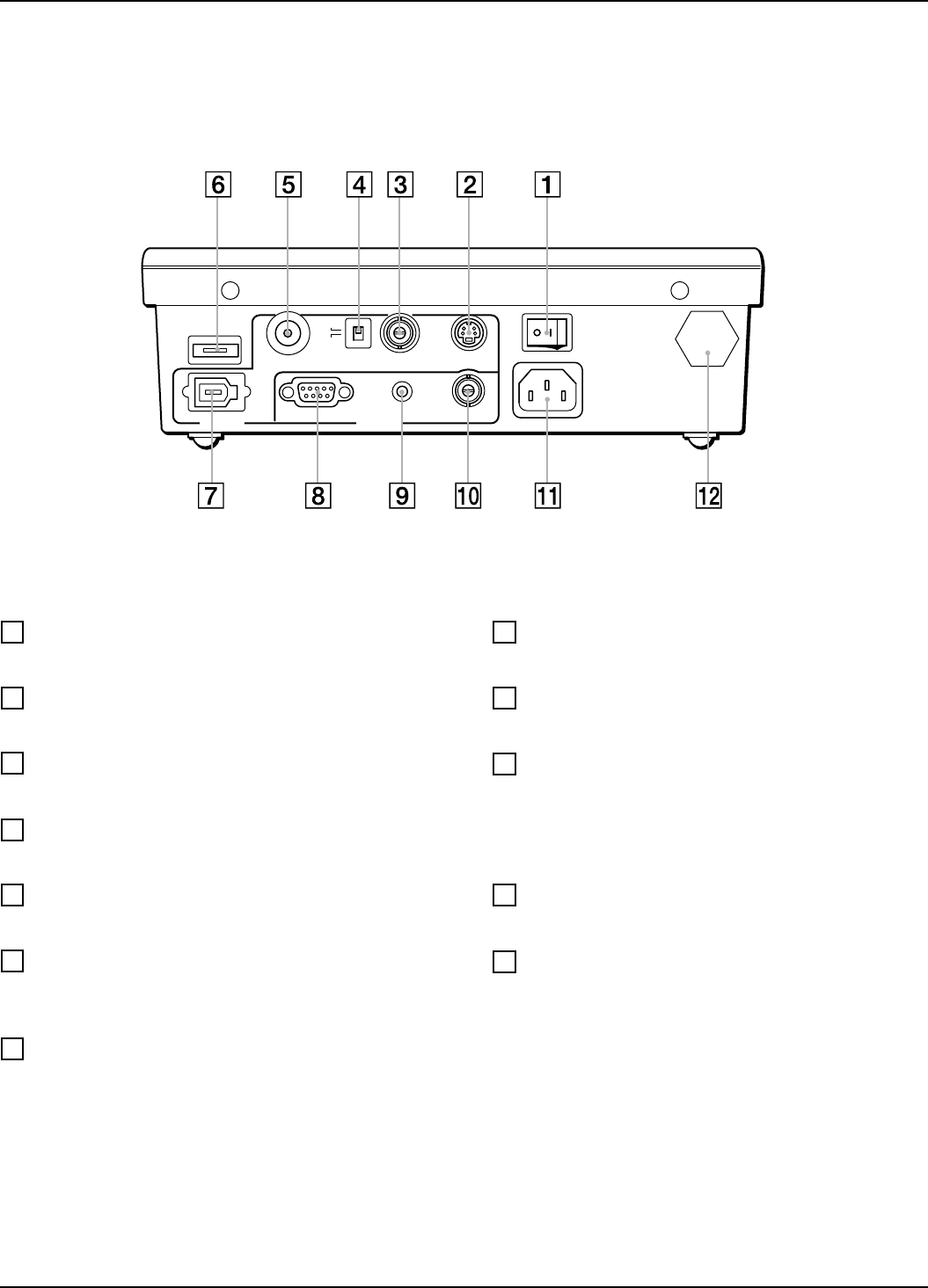
O/I (main power) switch
Switches the main power of the camera on or off.
S-VIDEO OUTPUT connector (mini DIN 4-pin)
Outputs an S-VIDEO (Y/C video) signal.
VIDEO OUTPUT connector (BNC-type)
Outputs a composite video signal.
NTSC/PAL select switch
Selects the output video signal from NTSC or PAL.
FLASH connector
Connects the cable of a flash lamp.
CAMERA connector (10-pin)
Connects to the CAMERA connector on the CHU using
the supplied camera cable.
IEEE 1394 (digital interface) connector
*
(6-pin)
Connects to a computer via an IEEE 1394 cable (not
supplied).
* This connector cannot be used for connection to camera equipment
with a DV connector.
* This connector is not compatible with bus power.
FS2 connector (D-sub 9-pin)
Reserved for future use.
FS1 connector (stereo mini jack)
Connects to the optional FS-20 foot switch.
TRIG IN (trigger input) connector (BNC-type)
Used when an external device, such as a slave unit,
generates the trigger signal. When using a flash lamp
in INPUT mode, connects a slave unit to the TRIG IN
connector.
~AC IN socket
Connects to the AC power cord.
Ventilation opening
CAMERA
IEEE
1394
FLASH
VIDEO S VIDEO
ONOFF
~ AC IN
TRIG IN
NTSC
PAL
FS1FS2
REMOTEOUTPUT
1
2
3
4
5
6
7
8
9
10
11
12
Camera Control Unit (CCU) Rear Panel
DXC_S500_1C.qxd 02.10.21 2:17 PM Page 10