37
Location and Functions of Parts and Controls
Overview
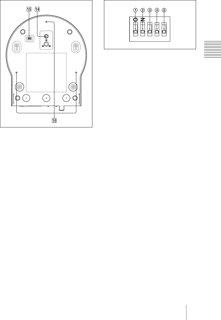
Bottom
N Tripod screw hole
O BOTTOM switches
Used for RS-232C and RS-422
switching, 9,600 bps and 38,400 bps
baud rate selection, D70 mode switching
and IR signal output setting. For detailed
information, refer to the Technical
Manual of the camera.
P Ceiling bracket mounting screw
holes
Setting of the BOTTOM switches
A D70 mode switch
Set to ON to use the VISCA command
for EVI-D70/D70P.
B IR OUT switch
Set to ON to enable output of the
receiver signals, which are transmitted
from the infrared remote commander via
the VISCA IN connector (page 50), or
set it to OFF to disable the output.
C RS-232C/RS-422 select switch
Set to ON to operate colour video
camera using the VISCA command via
the RS-422 interface. To change the
mode, turn off the camera (not including
standby mode) first, set the switch and
then turn on the camera again. Mode
switching is not possible while the
camera is turned on.
D Baud rate select switch
Set to ON for 38,400 bps or OFF for
9,600 bps. To change the mode, turn off
the camera (not including standby
mode) first, set the switch and then turn
on the camera again. The mode cannot
be switched while the camera is turned
on.
E Switch 5 (Not used)
Be sure to set this switch to OFF.
1
2
3
4
5


