


1-21 (E)
HDC-900/950 IMM
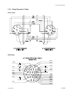
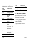
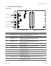
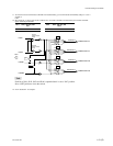
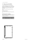
1-5. Switch Setting on the Boards
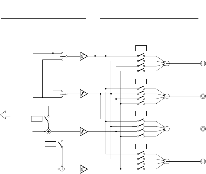
*1: The Tracker connector communicates to INCOM1 at the standard setting, yet it is communicable to INCOM2 by setting S1-1, S301-1
and S301-4
to ON.
*2: When setting S2-1 or S2-2 to ON, set bit1 and bit2 of S101, S102, S201 and S202 as shown below to prevent PGM1 and PGM2
signals from being mixed double.
S2-1 S101, 102, 201, 202 S2-2 S101, 102, 201, 202
bit1 bit12
ON ON ON ON
n
Each bit of S101, S102, S103 and S104 is opened when it is set to “ON” position.
Set to “OFF”position to close the switch.
*3: AU-271 board suffix -13 and higher.
INTERECOM CH1
bit1
bit2
bit3
bit4
bit1
bit2
bit3
bit4
bit1
bit2
bit3
bit4
bit1
S202
bit2
bit3
bit4
PGM 1
INCOM2
PGM1/2 swiitch
(Panel)
INCOM1
PGM1/2 swiitch
(Panel)
PGM 2
INCOM1
CCU
INCOM2
INTERECOM CH1
INTERECOM CH2
INTERECOM CH2
S201
S102
S101
S2-2
S2-1
PGM OUT
INCOM OUT
PGM OUT
INCOM OUT