


1-22 (E)
HDC-900/950 IMM
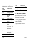
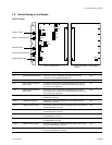
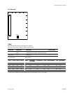
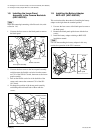
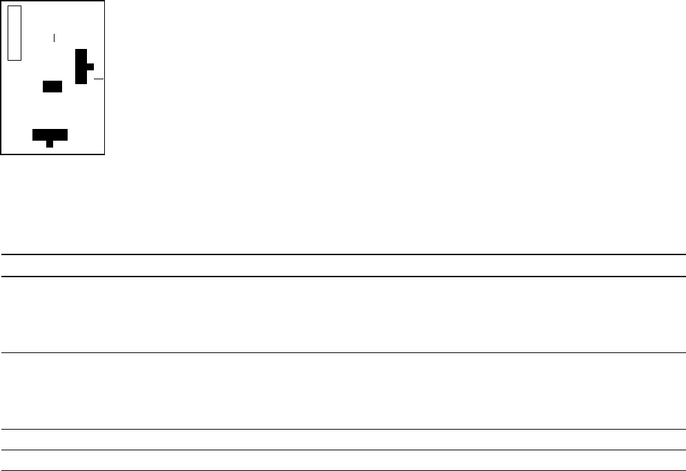
DU-104 board
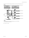
[Reference][Reference]
[Reference][Reference]
[Reference]
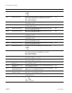
The switch setting on this board is valid only when connecting the RTS kit (optional) to the INTERCOM2 connector.
Ref. No. Name Contents Factory Setting
S1 RTS1 RTS 1/NORM/POW Selects the function of the RTS CH1 side. NORM
RTS 1 : RTS CH1 of the RTS kit operates as INCOM1 signal line.
NORM : Select NORM except when connecting to the RTS kit.
POW : RTS CH1 of the RTS kit operates as the power supply line
for the RTS belt pack.
S2 RTS2 RTS 2/NORM/POW Selects the function of the RTS CH2 side. NORM
RTS 2 : RTS CH2 of the RTS kit operates as INCOM2 signal line.
NORM : Select NORM except when connecting to the RTS kit.
POW : RTS CH2 of the RTS kit operates as the power supply line
for the RTS belt pack.
S4-1 RTS1 ON/OFF Switch ON to use the RTS CH1 as the INCOM1 signal line. OFF
S4-2 RTS2 ON/OFF Switch ON to use the RTS CH2 as the INCOM2 signal line. OFF
m
When not connecting the RTS kit, make the settings same as factory settings.
When S4-1 setting is ON, set S1 to RTS1, S201-1 through S201-4 on the AU-271 board to ON.
When S4-2 setting is ON, set S2 to RTS2, S201- through S201-4 on the AU-271 board to ON.
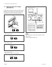
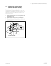
DU-104 board (A side)
S1
S4
S2
2
1
A
B
1-5. Switch Setting on the Boards