1-6 (E)
HDCU-900 MM
1-4. Functions of the Indicators on the
Boards
1-4-1. AT-141 Board
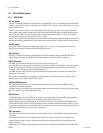
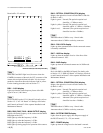
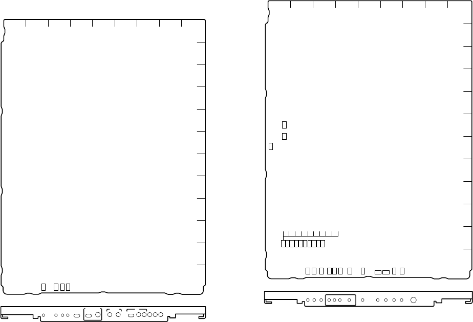
AT-141 board (A side and panel side)
D609 : GEN LOCK display
Lights up when external synchronization is established.
D611 : /1.001 display
Lights up when the frame frequency factor of the HD
signal is set to 1/1.001 times.
n
Set it with S603 on the AT-141 board. For details, refer to
Section 1-5-1, “AT-141 Board” of “Settings of Switches
and Controls on Boards” of the separate Installation and
Maintenance Manual.
D612 : REF IN display
Lights up when the reference signal is input to the REFER-
ENCE IN connector on the rear panel of the unit.
D802 : POWER display
Lights up when the voltage used on the board is normally
supplied.
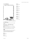
1-4-2. DPR-163 Board
Board suffix: -11 through -14
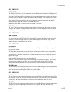
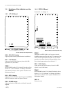
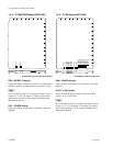
DPR-163 board (A side and panel side)
n
When D813 and D821 light in red, be sure to clean the
CAMERA connector of the unit, the CCU connector of the
camera side and optical/electrical cable. It is also recom-
mended to clean them when the indicators light in yellow.
For the cleaning procedure, refer to Section 1-7.
D801 : /1.001 display
Lights up when the frame frequency factor of the HD
signal is set to 1/1.001 times.
n
Set it with S603 on the AT-141 board. For details, refer to
Section 1-5-1, “AT-141 Board” of “Settings of Switches
and Controls on Boards” of the separate Installation and
Maintenance Manual.
D802 : 0
Factory use only
A
B
C
D
E
F
G
H
J
K
L
M
123456789
AT
POWER /1.001
FINE
HD BB
REMOTE
LOCAL
REFERENCE H
PHASE
MIC LEVEL
REF
IN
GEN
LOCK
NORM
MIN MIN
1
2
ENG PROD
PRIVATE
NORM
INCOM
SELECT
TALK
LEVEL
PGM
MIX
SIDE
TONE
2 WIRE
CANCEL
CH-1 CH-2
CCU
D609
D612
D611
D802
A
B
C
D
E
F
G
H
J
K
L
M
123456789
DPR
POWER
SYSTEM
POWER
/1.001 60 50 PSF
CHU LOCK
CCU CHU
540P 1035
OPTICAL
CONDITION
AUDIO PHASE
30 25 24
MAIN OUTPUT
D803
D801
D904
D907
D814
D810
D807
D805
D817
D819
D821
D813
D802
D804
D806
D808
D811
D812
D815
D818
D820
D822
D901
D902 D903
1-4. Functions of the Indicators on the Boards


