


COLOR IR CAMERACOLOR IR CAMERA User’s ManualUser’s Manual
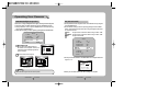
1716
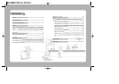
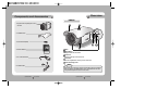
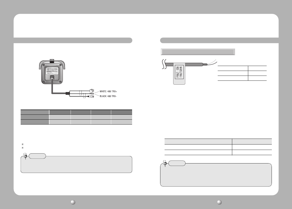
The recommended adaptor specification for SIR-4150N/P is DC 12V/4A.
Please check the standard power requirement before connecting to power.
Connecting to Power
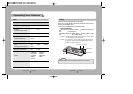
• As shown in the table above, voltage decreases as the wire gets longer.
Therefore use of an excessively long adaptor output line for connection to
the camera may affect the performance of the camera.
Standard voltage for camera operation : DC 12V±10%
There may be some deviation in voltage drop depending on the type of wire and the manufacturer.
When the resistance value of copper wire is at [20°C(68°F)]
Copper wire size(AWG) #24(0.22mm
2
) #22(0.33mm
2
) #20(0.52mm
2
) #18(0.83mm
2
)
Resistance value(Ω/m) 0.078 0.050 0.030 0.018
Voltage drop(V/m) 0.028 0.018 0.011 0.006
• Please must be used adaptor that meets the standard requirement.
• Please connect the power after installation.
Note
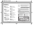
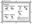
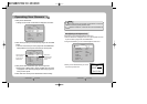
Using a RS-485 communication, it will be able to control the OSD menu at the
SAMSUNG TECHWIN System Controller or DVR.
(1) The case which it controls from the PC
Using a RS-485 converter, It connects to RS-485 CONTROL TERMINAL outside
camera and serial cable
EX) SERIAL PORT OF THE PC(COM1) — SERIAL CABLE -- RS-485 CONVERTER
-- RS-485 CONTROL TERMINAL
(2)The case which it controls from the DVR or System Controller
It connects the RS-485 CONTROL TERMINAL in the connection terminal of 485
control boards which are connected with the DVR or System Controller.
Connecting to RS-485 CONTROL TERMINAL
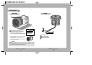
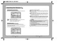
• When you construct external control systems for a camera control, please use to
the PELCO-D PROTOCOL.
• When you connecting to RS-485 CONTROL TERMINAL, please peel off the outer
skin inside the RS-485 CONTROL TERMINAL.
Notes
CONTROL TERMINAL
SPEC
WHITE (TRX+) RS-485+
BLACK (TRX-) RS-485-
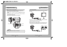
485 CONTROL BOARD CONNECTION TERMINAL RS-485 CONTROL TERMINAL
(+)CONNECTION TERMINAL WHITE (TRX+)
(-)CONNECTION TERMINAL BLACK (TRX-)
RS-485 communication control