


5
3. Camera Functions
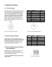
3.1 12-Pin Connector
The 12-pin Hirose connector is located on the rear
plate of the camera. All ground signals on pin # 1, 3,
5, 8, 10, and 12 are common grounds. Although
+12 V DC input is recommended on pin #2, this
camera should withstand +12 V ± 1V input voltage.
Make sure to set the NRM/ASM switch to NRM
position on rear plate for external HD and VD
locking. Apply TTL signal on HD (pin # 6) and VD
(pin # 7) inputs if necessary, see section 4.1 for
details. Figure 3 below shows a top view of the 12-
pin Hirose connector.
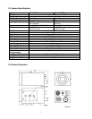
Pin No. Description Note
1 GND
2 +12V DC input
3 GND
4 Video
5 GND
6 External HD TTL
7 External VD/Strobe TTL
8 GND
9 N/C
10 GND
11 Integration control TTL
12 GND
Figure 3. 12-Pin Hirose Connector
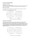
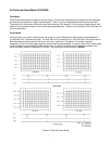
3.2 Shutter Speed Dial Switch
Shutter speed dial switch is located on the rear
panel (Figure 4). For normal shutter speeds, it has 9
different shutter speeds to select from. Position # 0
is standard scanning speed, 1/60 second. As
“Position #” goes higher, the shutter speed goes
higher and the video becomes darker.
Figure 4. Shutter Speed Dial Switch
Position
No.
Shutter
Speed (sec.)
Async
Capture (sec.)
0 1/60 (Off)
1 1/120 N/A
2 1/250 N/A
3 1/500 N/A
4 1/1000 N/A
5 1/2000 N/A
6 1/4500 N/A
7 1/6000 N/A
8 1/10000 N/A
9 1/31000 N/A
3.3 Normal and Asynchronous Capture
Mode (NRM/ASM)
NRM/ASM switch is located on camera rear plate.
Figure 5 shows all mode switch selections.
For normal operation, either with or without shutter
speed, NRM should be selected.
This camera DOES NOT provide asynchronous
capture feature.
Figure 5. Mode Switch