


12
•
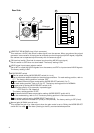
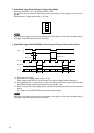
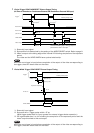
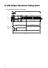
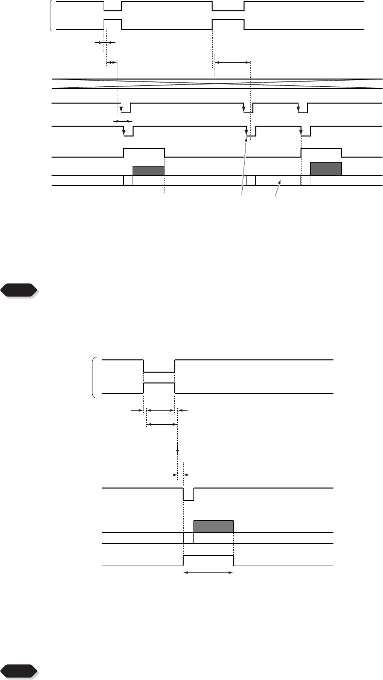
1 Pulse Trigger SYNC-NON RESET Picture Output Timing
(At Time of One-shot or Continuous External VD/Continuous External HD Input)
*1: Externally input signal
*2: Exposure time is determined by the setting of the MODE SELECT switch. Refer to page 9.
*3: Video is output at the falling edge of the internal VD following completion of the exposure
period.
The video and the VIDEO INDEX have a paired relationship.
NOTE
When the next trigger is input before completion of the output of the video corresponding to
the trigger, there will be an effect on the video.
About 1.7 µs
Video output
262.5H The internal VD falling edge is within the exposure
period and thus video is not output.
*
3
VIDEO INDEX
External VD IN*
1
External HD IN*
1
(Internal VD)
Trigger*
1
About 1H
Negative polarity mode
Positive polarity mode
Exposure period*
2
Exposure period*
2
About 1.7µs
About 98.7µs
Exposure completion
to 1H
VIDEO INDEX
VD OUT
*
3
Trigger*
1
262.5H
Negative polarity mode
Positive polarity mode
Exposure period*
2
•
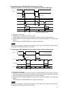
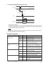
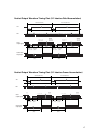
1 Pulse Width Trigger SYNC-RESET Picture Output Timing
*1: Externally input signal
*2: Exposure time = Trigger pulse width + 97 µs
(Valid trigger pulse width is 2 µs or greater for external trigger shutter operation.)
*3: VD is generated after 0 to 1H following the completion of the exposure period and the
video is synchronized to this and output.
NOTE
When the next trigger is input before completion of the output of the video corresponding to
the trigger, there will be an effect on the video.