


5
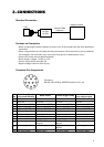
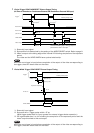
3. CONNECTIONS
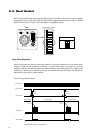
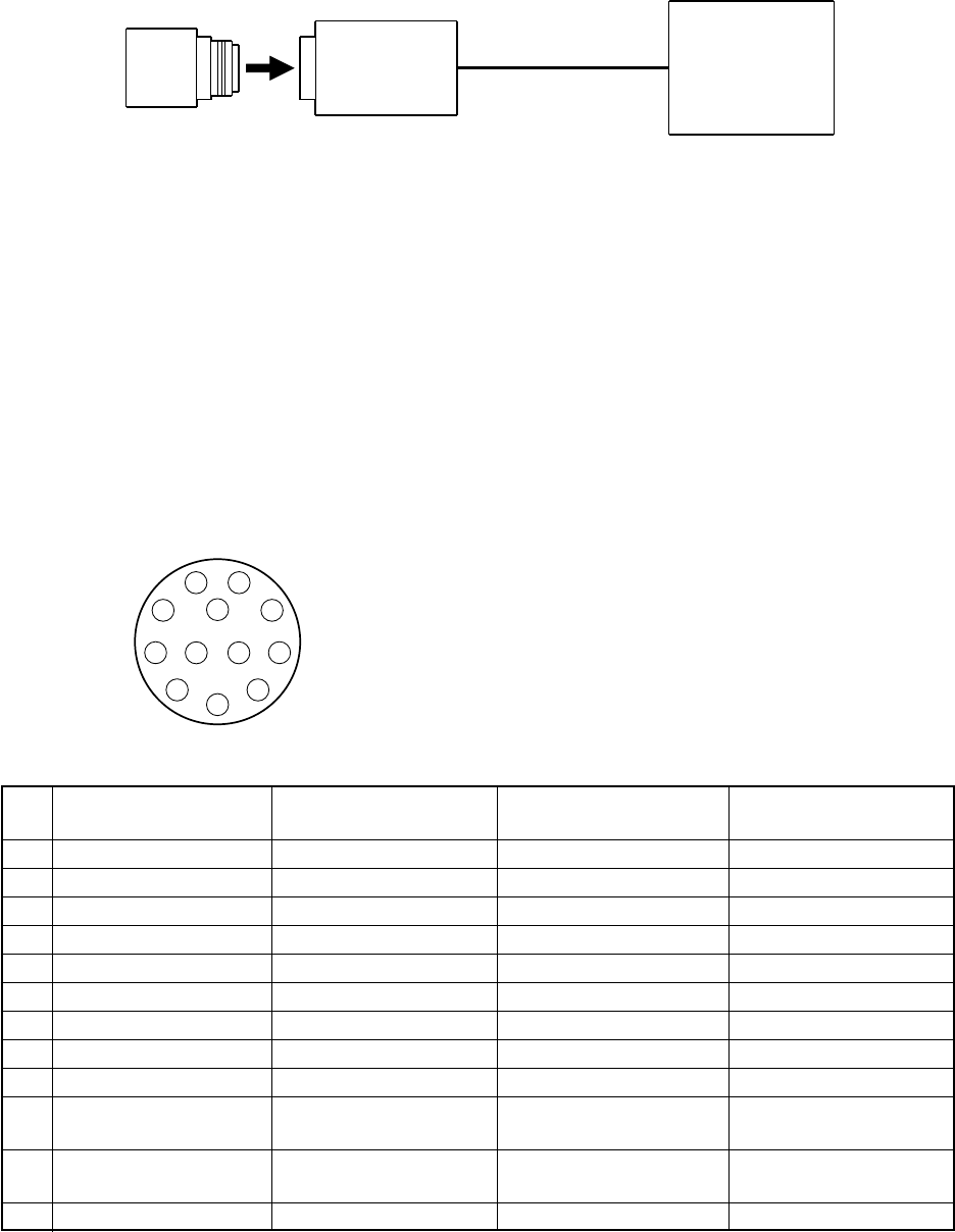
Standard Connection
Camera Cable
(optional)
Image processor
Lens
IK-53N
IK-52N
1
2
3
4
5
6
7
8
9
10
11 12
Cautions on Connection
• When connecting the camera cables, be sure to turn off the camera and the other equipment
connected.
• When using another lens, the best camera performance of this camera may not be obtained.
(For example, low resolution may occur, and flare, ghost or shading may occur)
• Use the DC power source described below.
• Power supply voltage: +10.5V to +15V
• Current rating: More than 830 mA
• Ripple voltage: Less than 50 mV(p–p)
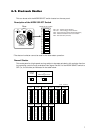
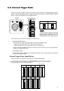
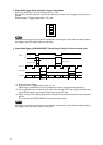
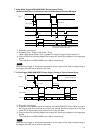
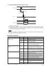
Connector Pin Assignments
Pin
No.
1
2
3
4
5
6
7
8
9
10
11
12
External synchroniza-
tion mode (HD/VD)
GND
DC+12V
Video output (GND)
Video output (signal)
HD input (GND)
HD input (signal)
VD input (signal)
GND
–
–
–
VD input (GND)
Reset restart
GND
DC+12V
Video output (GND)
Video output (signal)
HD input (GND)
HD input (signal)
Reset (signal)
GND
–
VIDEO INDEX output
(signal)
–
Reset (GND)
External trigger mode
GND
DC+12V
Video output (GND)
Video output (signal)
HD input (GND)
HD input (signal)
VD input (signal)
GND
–
VIDEO INDEX output
(signal)
Trigger pulse input
(signal)
VD input (GND)
Connector:
HR10A–10R–12PB by HIROSE electronics Co. Ltd
Internal synchroniza-
tion output signal
GND
DC+12V
Video output (GND)
Video output (signal)
HD output (GND)
HD output (signal)
VD output (signal)
GND
–
–
–
VD output (GND)