


7
1
8
2
4
6
7
5
9
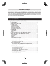
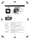
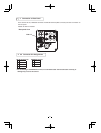
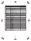
Optical area
HD-SDI terminal
DISP button
REMOTE
terminal
3
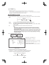
FORMAT switch
Mounting holes M3
Mounting holes M2
PAGE button
[ Rear ][ Front ]
[ Bottom ]
MENU UP button
MENU DOWN button
DATA UP (AWB) button
DATA DOWN button
DC IN 12V terminal
13
11
12
10
3. NAMES AND FUNCTIONS
Optical area
DISP button
PAGE button
MENU UP button
MENU DOWN button
DATA UP (AWB) button
DATA DOWN button
DC IN 12V terminal
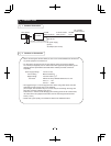
FORMAT switch
(1) Effective scanning lines Switches between 1080i and 720p. (Factory default setting: 1080i)
* Switching the effective scanning between 1080i and 720p changes the angle
of view on a monitor.
(2) Vertical frequency Switches between 59.94 Hz and 50 Hz. (Factory default setting: 59.94 Hz)
REMOTE terminal
Mounting holes M3
Mounting holes M2
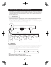
The protection cap is attached on the lens mount portion. After removing the cap,
mount the lens. Be careful not to scratch or touch the optical area.
Used when switching the display.
Used when switching to the menu and when selecting the menus.
Select the function to be confirmed or changed on the menu.
Select the function to be confirmed or changed on the menu.
Changes the value of the function selected by the MENU (UP/DOWN) button. (Also
used when performing AWB.)
Changes the value of the function selected by the MENU (UP/DOWN) button.
Accepts a DC power input (12V).
To connect to a RS-232C device for remote control of the camera.
Used to attach the camera to a mount.
Used to attach the camera to a mount.When using a tripod, attach the supplied
tripod mount to these holes.
㽲
㽳
㽴
㽵
㽶
㽷
㽸
㽹
㽺
㽻
HD-SDI terminal Outputs a serial digital signal. (BNC connector)
㽼
㽽
㽾