


14
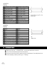
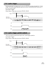
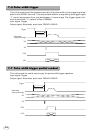
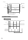
7.6 Pulse width trigger
This is the mode to set the exposure period by the pulse width of the trigger signal ap-
plied to the DIGITAL terminal. This accumulates electric charge taking the trigger signal
“L” period as exposure time, and developes a 1-frame image. The trigger signal mini-
mum pulse width (“L” period) is 20µs (1/50000s).
Input signal: Trigger
Output signal: Video data, pixel clock, FEN/VD, LEN/HD
HD
Trigger
VD
FEN
LEN
Video data
(video period image)
Exposure period
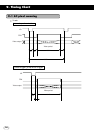
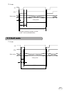
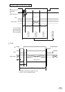
7.7 Pulse width trigger partial readout
This is the mode for partial scanning by the pulse width trigger operation.
Input signal: Trigger
Output signal: Video data, pixel clock, FEN/VD, LEN/HD
HD
VD
FEN
LEN
Trigger
Video data
(video period image)
Exposure period