


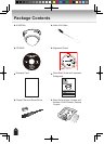
14
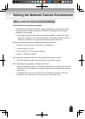
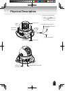
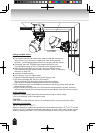
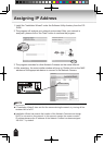
Wall Mount
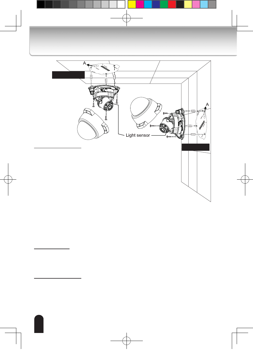
Ceiling Mount
Ceiling and Wall mount
Notes:
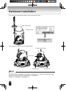
l
The included screws and anchors are used to install the camera to a
solid surface. (e.g. concrete) If installing on loose or thin material
surfaces , use the appropriate anchors (not included) with the screws.
l
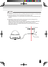
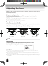
If
possible, point the TOSHIBA logo towards the eld of view.
The adjustment range of PAN is indicated on the alignment sticker.
l
When installing the camera to the wall, don’t turn the lens cover,
and make sure the light sensor location as shown. (Refer to “Adjusting
the Lens” on page 20.)
l
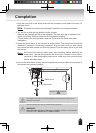
Install the camera securely.
l
Use Category (Cat) 5 or higher cable.
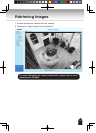
1. Attach the supplied alignment sticker to the ceiling or wall.
2. Drill three pilot holes (Ø0.19inch×1.02inches(D)
(Ø4.8mm×26mm(D))) through the three circles on the sticker.
Then hammer the three supplied plastic anchors into the holes.
3. Drill a cable hole A(Ø1.1inch (Ø28mm)) as shown in the above picture, and lead the
cables through this hole.
4. Align the three mounting holes of the Camera with the three plastic anchors; insert the
included three screws to the corresponding holes and tighten them with a driver securely.
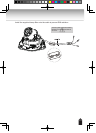
Cable installation
If possible, lead all cables behind the camera body through a wall or ceiling.
If this is not possible, route it through the side.
CAUTION:
If the cable is routed outdoors, ensure UL certicated tube is used to protect the cable.
Operating environment
-20
o
C ~ +50
o
C {-4
o
F ~ 122
o
F}
When the camera is installed and operated in low temperatures below -10
o
C{14
o
F}, normal
images may not be obtained immediately after startup. In such a case, wait until the camera
warms up (taking more than 1 hour) and start adjustment after turning on the power again.
1414